


3 digits Digital volt meter
#digital voltmeter
#PIC16F676
#7-segment display
#ADC
#voltage measurement
#microcontroller
#analog signal
#DC current
#electronics
#circuit

Description: This is a simple 3-digit digital voltmeter. The PIC16F676 microcontroller is utilized to read an analog signal (voltage) and display the value on a 3-digit 7-segment display. It can also measure DC current using a parallel Rshunt, although that aspect is not described here. Most PIC microcontrollers feature an 8-bit/10-bit on-chip Analog to Digital Converter (ADC) module. In this project, the PIC16F676, which has a 10-bit ADC with 8 channels, is employed; however, only one channel is used for measuring the voltage input, while the other pins are configured as digital I/O. In the schematic, the input voltage is divided by resistors R1 and R2 (forming a voltage divider). A variable resistor (VR1) is connected in parallel with R2 to adjust the appropriate display full-scale voltage. The divided input voltage is connected to AN3 (RA4), which is set as an analog input.
The digital voltmeter circuit employs the PIC16F676 microcontroller, which is central to its operation. The microcontroller's ADC allows for the conversion of the analog voltage signal into a digital format suitable for display. The circuit design includes a voltage divider composed of resistors R1 and R2 to scale down the input voltage to a range compatible with the ADC. This is critical for ensuring that the voltage does not exceed the ADC's maximum input level.
The variable resistor VR1 serves as a calibration tool, enabling the user to fine-tune the maximum voltage that the display can represent. By adjusting VR1, the output from the voltage divider can be set to match the desired full-scale reading on the 7-segment display, enhancing measurement accuracy.
The choice of using the AN3 (RA4) pin for analog input is significant, as it is one of the designated ADC channels in the PIC16F676 microcontroller. This configuration allows for efficient use of the available channels, leaving the remaining pins free for digital input/output operations. The circuit's simplicity facilitates easy integration into various applications, such as battery monitoring or power supply testing, where voltage measurement is essential.
In summary, this digital voltmeter circuit is an effective implementation of a microcontroller-based measurement system, utilizing the capabilities of the PIC16F676 to achieve accurate voltage readings displayed on a 7-segment display. The design considerations, including the voltage divider and calibration adjustments, contribute to its functionality and versatility in practical applications.This is simple 3-digits digital volt meter. PIC16F676 used to read analog signal(voltage) and display the value on 3-digits 7-segment. You can apply to mesasure DC currant with parallel Rshunt but I`m not descript here. As we know the most of PIC microcontroller has 8-bit/10-bit on-chip Analog to Digital converter module. In this project I use PIC16 F676 which have ADC 10-bits 8 channel but this project use only one channel for measure voltage input for other pin set as digital I/O. From the schematic above the input voltage divided by R1 and R2 (voltage divider). VR1 parallel with R2 use to adjust appropriate display full scale voltage. The divided input voltage will connected to AN3(RA4) which set as analog input.
The digital voltmeter circuit employs the PIC16F676 microcontroller, which is central to its operation. The microcontroller's ADC allows for the conversion of the analog voltage signal into a digital format suitable for display. The circuit design includes a voltage divider composed of resistors R1 and R2 to scale down the input voltage to a range compatible with the ADC. This is critical for ensuring that the voltage does not exceed the ADC's maximum input level.
The variable resistor VR1 serves as a calibration tool, enabling the user to fine-tune the maximum voltage that the display can represent. By adjusting VR1, the output from the voltage divider can be set to match the desired full-scale reading on the 7-segment display, enhancing measurement accuracy.
The choice of using the AN3 (RA4) pin for analog input is significant, as it is one of the designated ADC channels in the PIC16F676 microcontroller. This configuration allows for efficient use of the available channels, leaving the remaining pins free for digital input/output operations. The circuit's simplicity facilitates easy integration into various applications, such as battery monitoring or power supply testing, where voltage measurement is essential.
In summary, this digital voltmeter circuit is an effective implementation of a microcontroller-based measurement system, utilizing the capabilities of the PIC16F676 to achieve accurate voltage readings displayed on a 7-segment display. The design considerations, including the voltage divider and calibration adjustments, contribute to its functionality and versatility in practical applications.This is simple 3-digits digital volt meter. PIC16F676 used to read analog signal(voltage) and display the value on 3-digits 7-segment. You can apply to mesasure DC currant with parallel Rshunt but I`m not descript here. As we know the most of PIC microcontroller has 8-bit/10-bit on-chip Analog to Digital converter module. In this project I use PIC16 F676 which have ADC 10-bits 8 channel but this project use only one channel for measure voltage input for other pin set as digital I/O. From the schematic above the input voltage divided by R1 and R2 (voltage divider). VR1 parallel with R2 use to adjust appropriate display full scale voltage. The divided input voltage will connected to AN3(RA4) which set as analog input.

Microcontroller Relay Driver and Interface
Many microcontroller designs typically integrate various interfacing methods. A microcontroller (µC) system can be viewed as a system that reads from inputs.
Microcontroller systems are versatile platforms that facilitate the integration of multiple interfacing methods to interact with various peripherals and...
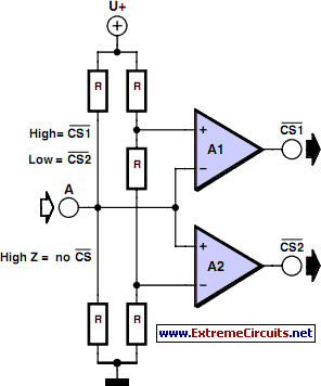
Multitasking Pins circuit
It is entirely logical that low-cost miniature microcontrollers have fewer pins than their larger counterparts, sometimes too few. Consideration has been given to how to economize on pins by making them perform the work of several. It was noted that...

Simple Analog to Digital Converter (ADC)
Normally, an analog-to-digital converter (ADC) requires interfacing through a chip to convert analog signals into digital format. This necessitates both hardware and software, resulting in increased complexity and overall cost. The circuit presented here is configured around the ADC 0808,...

Digital Calender Circuit
This is a digital calendar circuit that utilizes a microcontroller to display the date, day, and month on an LED display. The entire system is managed by an 8-bit microcontroller, which operates based on a program embedded in its ROM....

Coulomb meter
Another cause of voltage drift is the input current of IC1, which slowly charges capacitor C1. This effect is particularly noticeable when the output voltage is approximately 0 volts.
The circuit in question involves an integrated circuit (IC1) whose input current...

delay
This article outlines the construction of a simple microcontroller-based delay circuit designed for photographic applications, such as drop or high-speed photography. It is capable of controlling the trigger lag for cameras and flash units, generating periodic trigger pulses, or managing...

ADC 207 Flash Converting Schematic Diagram
The ADC 207 is the first analog-to-digital converter to utilize Flash Converting technology based on an advanced high-speed VLSI 1.2-micron CMOS process. This innovative process enhances the unique capabilities of the ADC 207, providing excellent speed, good linearity, and stable...
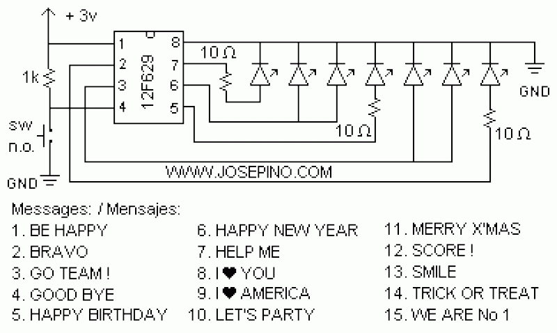
ON/OFF button using Microcontrollers
Using a switch to power up your microcontroller projects may not be a good idea if you need to "wake" the PIC during some events. For example: A metal detector sends a pulse indicating a car is ready to enter...
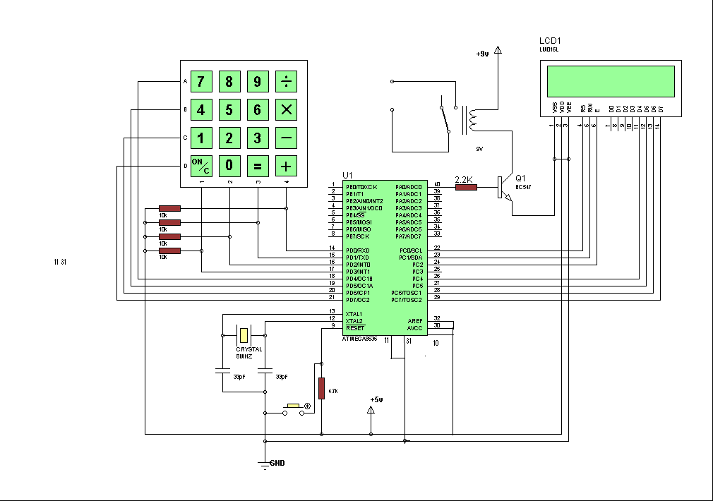
Secured room access system
Security is a primary concern in daily life, and an access control system is a crucial component of a security framework. The microcontroller-based digital lock described here is an access control system that permits only authorized individuals to enter a...