


AD574A unipolar and bipolar input circuit b
#AD574A
#ADC
#12-bit
#successive approximation
#microprocessor interface
#analog voltage
#unipolar
#bipolar
#data conversion
#high performance

Description: The AD574A is a high-performance 12-bit successive approximation analog-to-digital (A/D) converter that can interface directly with an 8 or 16-bit microprocessor bus. The input to the AD574A can be either unipolar or bipolar. The unipolar analog input voltage range is 0-10V or 0-20V, while the bipolar input voltage range is ±5V or ±10V. When using a unipolar input, the BIP OFF termination should be set to 0V. The circuit connection for this configuration is illustrated in the accompanying figure, where the BIP OFF side connects through a 100nF capacitor to ground, and the resistor RP1 allows for zero adjustment. For bipolar input, the BIP OFF termination voltage is set to +10V, with the circuit connection depicted in another figure. In this configuration, the BIP OFF end connects through a 1000Ω resistor (RP2) to the reference voltage, which is also tied to the +10V voltage connections.
The AD574A A/D converter operates by converting an analog input signal into a digital representation with a resolution of 12 bits. This level of precision is suitable for various applications, including industrial automation, data acquisition systems, and instrumentation. The device can handle two types of input signals: unipolar and bipolar, making it versatile for different operational requirements.
For unipolar applications, the converter accepts voltage levels ranging from 0V to 10V or 0V to 20V. In this configuration, it is essential to ensure that the BIP OFF termination is set to 0V to avoid erroneous readings. The circuit design includes a 100nF capacitor for electrical grounding, which helps to stabilize the input signal and filter out noise. The resistor RP1 serves a crucial role in providing a zero adjustment, allowing for calibration of the output to ensure accurate digital representation.
In bipolar mode, the AD574A can accommodate input voltages of ±5V or ±10V. The BIP OFF termination voltage is adjusted to +10V, facilitating the conversion of negative voltage signals. The circuit design in this mode connects the BIP OFF end through a 1000Ω resistor (RP2) to the reference voltage, ensuring that the converter can accurately interpret both positive and negative voltage levels. This configuration is particularly useful in applications where the signal may swing above and below ground, such as in audio processing or sensor data acquisition.
Overall, the AD574A's flexible input configurations and high-resolution capabilities make it a valuable component in modern electronic systems, providing reliable data conversion for a wide range of applications. Proper circuit design and component selection are critical to maximizing the performance and accuracy of the A/D conversion process.AD574A is a high performance 12-bit successive approximation. A/D converter can be directly with the 8 or 16-bit microprocessor bus interface. Input into AD574A analog voltage, either unipolar or may be bipolar. Unipolar analog input voltage range of O-lOV or 0-20V} bipolar input voltage range is 5v or 20V. When unipolar input should BIP OFF Termination ov. A circuit connection shown in FIG. Figure BIP OFF side through the 100n electrical grounding resistance by RP1 can also be zero adjustment. When bipolar input, BIP OFF + lov termination voltage, circuit connection shown in Figure b. Circuit BIP OFF end by 1000 and the resistor RP2 REF, OU end rhyme + 10V voltage connections
The AD574A A/D converter operates by converting an analog input signal into a digital representation with a resolution of 12 bits. This level of precision is suitable for various applications, including industrial automation, data acquisition systems, and instrumentation. The device can handle two types of input signals: unipolar and bipolar, making it versatile for different operational requirements.
For unipolar applications, the converter accepts voltage levels ranging from 0V to 10V or 0V to 20V. In this configuration, it is essential to ensure that the BIP OFF termination is set to 0V to avoid erroneous readings. The circuit design includes a 100nF capacitor for electrical grounding, which helps to stabilize the input signal and filter out noise. The resistor RP1 serves a crucial role in providing a zero adjustment, allowing for calibration of the output to ensure accurate digital representation.
In bipolar mode, the AD574A can accommodate input voltages of ±5V or ±10V. The BIP OFF termination voltage is adjusted to +10V, facilitating the conversion of negative voltage signals. The circuit design in this mode connects the BIP OFF end through a 1000Ω resistor (RP2) to the reference voltage, ensuring that the converter can accurately interpret both positive and negative voltage levels. This configuration is particularly useful in applications where the signal may swing above and below ground, such as in audio processing or sensor data acquisition.
Overall, the AD574A's flexible input configurations and high-resolution capabilities make it a valuable component in modern electronic systems, providing reliable data conversion for a wide range of applications. Proper circuit design and component selection are critical to maximizing the performance and accuracy of the A/D conversion process.AD574A is a high performance 12-bit successive approximation. A/D converter can be directly with the 8 or 16-bit microprocessor bus interface. Input into AD574A analog voltage, either unipolar or may be bipolar. Unipolar analog input voltage range of O-lOV or 0-20V} bipolar input voltage range is 5v or 20V. When unipolar input should BIP OFF Termination ov. A circuit connection shown in FIG. Figure BIP OFF side through the 100n electrical grounding resistance by RP1 can also be zero adjustment. When bipolar input, BIP OFF + lov termination voltage, circuit connection shown in Figure b. Circuit BIP OFF end by 1000 and the resistor RP2 REF, OU end rhyme + 10V voltage connections

analog-to-digital converters (ADCs)
Analog-to-digital converters (ADCs), printed-circuit board (PCB), microcontroller or digital signal processor (DSP), total-harmonic-distortion (THD), signal-to-noise ratio (SNR).
Analog-to-digital converters (ADCs) are essential components in modern electronic systems, enabling the conversion of analog signals into digital form for processing by microcontrollers or...

Flash ADC
Also known as the parallel A/D converter, this circuit is the simplest to understand. It consists of a series of comparators, each comparing the input signal to a unique reference voltage. The outputs of the comparators connect to the inputs...

Bipolar power supply for battery instruments
To generate regulated ±5-V supplies from a pair of dry batteries, the circuit shown in Fig. 1 is commonly utilized. To protect against inadvertent reverse connection of a battery, a diode in series with each battery would create an unacceptable...
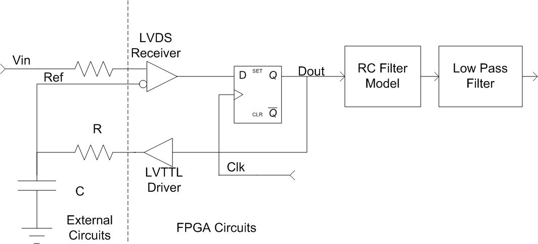
ADC In An FPGA
This content is highly technical and involves Analog-to-Digital Converters (ADCs), Field Programmable Gate Arrays (FPGAs), and advanced electrical design. If this topic does not resonate with you, it is advisable to skip the remainder of this blog post. An update:...

Flash ADC
Also known as the parallel A/D converter, this circuit is the simplest to understand. It consists of a series of comparators, each comparing the input voltage to a reference voltage.
The parallel analog-to-digital (A/D) converter is a fundamental circuit in electronics,...

Current spreading circuit diagram of a bipolar output
Current spreading bipolar output when the circuit diagram is as follows.
The circuit described involves a current spreading bipolar output configuration. This type of circuit is typically used in applications requiring efficient current distribution across multiple output paths, often seen in...

Three Bit flash Analog to Digital Converter Circuit
The flash type converter is the simplest and fastest type of analog-to-digital converter. The entire digital output word is available immediately after the propagation delay time of the comparators and the encoding logic gates. A typical conversion time for a...
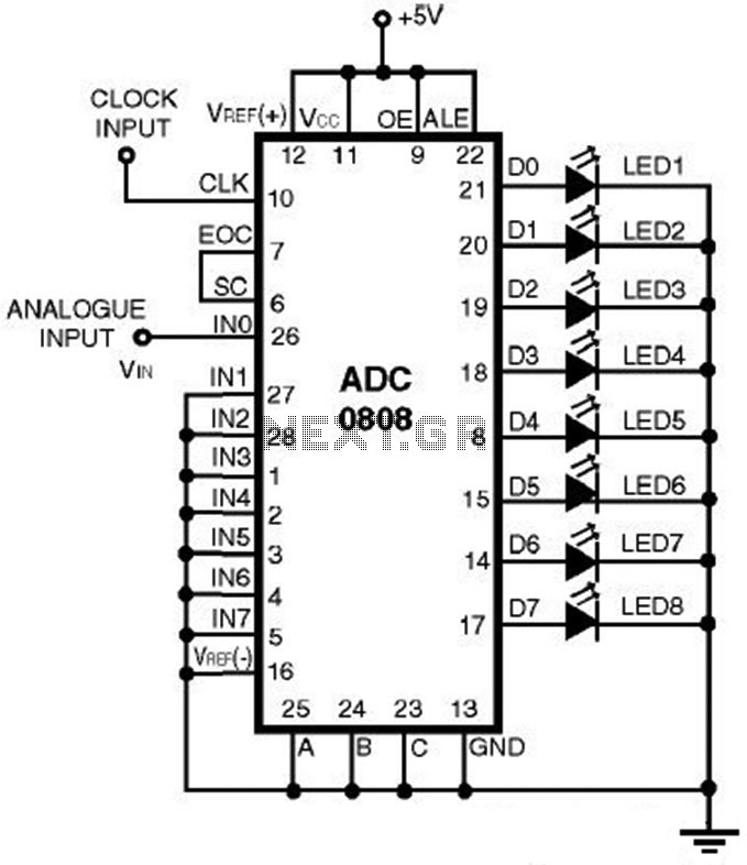
ADC0808 - Simple Analoque to Digital Converter
This is a straightforward analog-to-digital converter circuit utilizing an 8-bit analog-to-digital converter (ADC0808). Typically, an analog-to-digital converter (A/D Converter / ADC) necessitates interfacing with a microprocessor to convert analog signals.
The ADC0808 is a widely used 8-bit A/D converter that can...
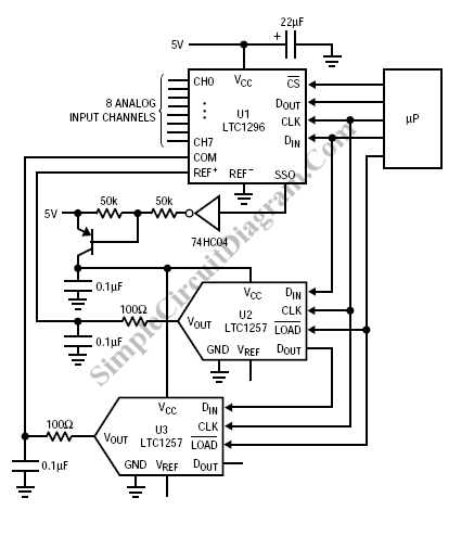
Autoranging Circuit
To extend the measurement range of an available ADC (analog to digital converter), autoranging can be utilized. If implemented on multiplexed input, this...
Autoranging is a technique employed in electronic measurement systems to automatically adjust the range of an analog-to-digital converter...