


Analogue to digital converter circuit
#analogue to digital converter
#ADC
#4 digits
#IN4146 diodes
#POLYSTYRENE
#NPO
#frequency conversion
#measurement
#electronics

Description: The simple 4-digit converter circuit has an output count of 1, designed for a frequency range from f-IMHz to 10.000 MHz. All diodes used in the circuit are IN4146 "POLYSTYRENE" NPO. The circuit utilizes the LF398 at the input stage.
The described 4-digit converter circuit operates as a frequency counter, capable of accurately measuring and displaying frequencies within the specified range. The LF398, a precision analog-to-digital converter (ADC), serves as the input component, converting the analog frequency signal into a digital representation. The LF398 is known for its high-speed performance and low power consumption, making it suitable for applications where rapid and efficient frequency counting is required.
The choice of IN4146 diodes, recognized for their low leakage current and high-speed switching capabilities, enhances the circuit's performance by ensuring minimal signal distortion and maintaining signal integrity. The use of "POLYSTYRENE" NPO capacitors in the design further contributes to the stability and accuracy of the circuit, as these capacitors exhibit low dielectric losses and excellent temperature stability.
The output count of 1 indicates that the circuit provides a single digital output, which can be interfaced with a display module or microcontroller for real-time frequency readouts. The overall design is optimized for simplicity, reliability, and precision, making it suitable for various applications in telecommunications, signal processing, and laboratory measurements. The circuit can be further enhanced by incorporating additional features, such as averaging or filtering, to improve measurement accuracy in noisy environments.That simple 4 digits converter circuit has OUTPUT COUNT = 1 according to my f-IMHz to 10.000. All diodes are IN4146 "POLYSTYRENE" NPO. The circuit uses the LF398 at input.
The described 4-digit converter circuit operates as a frequency counter, capable of accurately measuring and displaying frequencies within the specified range. The LF398, a precision analog-to-digital converter (ADC), serves as the input component, converting the analog frequency signal into a digital representation. The LF398 is known for its high-speed performance and low power consumption, making it suitable for applications where rapid and efficient frequency counting is required.
The choice of IN4146 diodes, recognized for their low leakage current and high-speed switching capabilities, enhances the circuit's performance by ensuring minimal signal distortion and maintaining signal integrity. The use of "POLYSTYRENE" NPO capacitors in the design further contributes to the stability and accuracy of the circuit, as these capacitors exhibit low dielectric losses and excellent temperature stability.
The output count of 1 indicates that the circuit provides a single digital output, which can be interfaced with a display module or microcontroller for real-time frequency readouts. The overall design is optimized for simplicity, reliability, and precision, making it suitable for various applications in telecommunications, signal processing, and laboratory measurements. The circuit can be further enhanced by incorporating additional features, such as averaging or filtering, to improve measurement accuracy in noisy environments.That simple 4 digits converter circuit has OUTPUT COUNT = 1 according to my f-IMHz to 10.000. All diodes are IN4146 "POLYSTYRENE" NPO. The circuit uses the LF398 at input.

ProfiLab-Expert 4.0
The ProfiLab-Expert software allows you to develop your own digital or analogue measuring technology projects. It doesn't matter if you want to create analogue measurements or digital controls - you can realize it all. And for all this you don't...

What is analog to digital converter ADC using LM324 IC
The process of converting an analog voltage into an equivalent digital signal is known as Analog to Digital Conversion (ADC). An ADC is an electronic circuit that converts its analog input to a corresponding binary value. The output depends on...

Tracking-adc
The analog input is connected to the span resistor of a Digital-to-Analog Converter (DAC). The voltage range of the analog input is selectable, mirroring the output voltage range of the DAC. The current flowing through the ladder termination resistance, which...

The ICL7135 Integrating A/D Converter Functional Diagram and Datasheet
The schematic below shows the ICL7135 integrating analog-to-digital converter (ADC) functional diagram. According to the datasheet, an integrating converter is the right choice for panel meters and digital voltmeter applications. It can also be used for reducing line frequency noise...
RealView 2.0
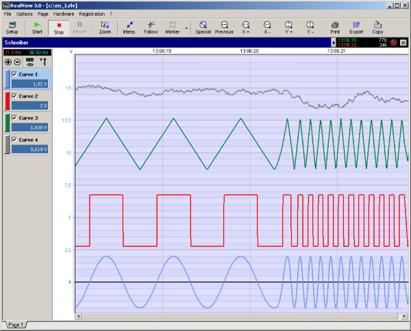
RealView is a measurement application, which records and plots measured values from analogue hardware devices in real-time. Several curves can be plotted into a single diagram. Several diagrams can be arranged on one or more pages if necessary. Plot options...

Successive Approximation ADC
An analog-to-digital converter is a device that converts a continuous quantity to a discrete time digital representation. An ADC may also provide an isolated measurement. An analog signal is any continuous signal where the time-varying feature represents another time-varying quantity....

Three Bit flash Analog to Digital Converter Circuit
The flash type converter is the simplest and fastest type of analog-to-digital converter. The entire digital output word is available immediately after the propagation delay time of the comparators and the encoding logic gates. A typical conversion time for a...
Dynamic Testing of High-Speed ADCs Part 2
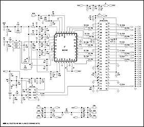
The following article is a continuation of the application note titled "Defining and Testing Dynamic Parameters in High-Speed ADCs, Part 1." It outlines the test conditions and setup recommendations necessary for effectively measuring the dynamic performance parameters of high-speed analog-to-digital...

Half-flash-adc
A conversion technique known as half-flash combines the speed advantages of flash conversion with the circuitry efficiency of successive approximation. In an 8-bit half-flash converter, two 4-bit flash converter sections are integrated. The upper flash converter compares the input signal...