


analyser

Description: The information provided is primarily aimed at home brewers interested in constructing an analyzer or designing their own based on established design principles. It is not intended for commercial applications. A cautionary note is necessary for those wishing to build the analyzer: ensure all components are readily available. The original design objective was to utilize easily obtainable components; however, some key components have become obsolete and difficult to source. The accompanying table may assist in identifying equivalents or potential suppliers. The voltage-controlled oscillator (VCO) is a Hartley oscillator tuned by a BB212 varicap, with its frequency regulated by an MC145170 synthesizer. The clock frequency of the synthesizer is 10.240 MHz, which is divided by 1024 to yield a 10 kHz reference frequency, allowing the VCO to be tuned in increments of 10 kHz. The controller software permits selection of the actual step size from a sequence of 10, 20, 100, 200, 500, or 1000 kHz. The VCO signal is directed to two NE602 mixers, with the local oscillator (LO) signal generated by a Colpitts crystal oscillator operating at 48 MHz. Two RC combinations of 100 ohms and 33 pF provide the necessary +45° and -45° phase shifts. Each mixer output is buffered by an emitter follower, with the second mixer also supplying the measurement signal. The outputs of the NE602s are used as single-ended outputs, with either I or Q selected by a diode switch and sent to a fifth-order low-pass filter (LPF) at the LO input of a synchronous detector, which is also an NE602. Another diode switch selects either voltage or current to connect to the detector's input. The differential output of the detector is sent to a differential amplifier on the controller board, with the output connected to one of the analog-to-digital converter (ADC) inputs. This first amplifier is followed by a second amplifier with a gain of 11, whose output connects to a second ADC input. The controller utilizes the second amplified signal to implement a straightforward auto-scaling method. A rotary encoder is employed to set the frequency, while a pushbutton functions as a function key. When pressed and held, the encoder adjusts the step size; when released, it controls the frequency. Pressing and releasing the function key selects menu items. The display mode allows representation of impedance in either series equivalent (Rs + jXs) or parallel equivalent (Rp // jXp) formats. In addition to complex impedance, the analyzer computes equivalent inductance (in Henries) or capacitance (in picofarads), as well as the standing wave ratio (SWR). The backlight intensity is managed through pulse-width modulation (PWM), with the PWM signal generated by one of the controller's timers, providing an efficient means of controlling the current supplied to the LED backlight. The built-in UART of the controller facilitates communication with a PC, primarily for frequency scanning purposes. The commands sent by the PC include three numeric values: start frequency, end frequency, and step size, all measured in 10 kHz units. For instance, "400 900 10" instructs the analyzer to perform a scan from 4 MHz to 9 MHz in 100 kHz steps. The results are reported in the format of frequency in kHz, resistance in ohms, and reactance in ohms, with the representation depending on the display mode. After completing a scan, the frequency resets to its original setting. The controller's UART is designed to work with level shifters like the MAX232, reversing the polarity of the input and output compared to the RS232 TX and RX lines. Simple transistor inverters are effective in most cases. The baud rate is fixed at 4800 bps, which is the highest rate reliably achievable with the internal RC clock generator. It is essential to decouple the collectors of all transistors directly to the ground plane using 1 nF or 10 nF chip capacitors.
The analyzer circuit design features a robust architecture that integrates various components for precise measurement and analysis of impedance. The use of a Hartley oscillator as the VCO allows for fine-tuning of frequency, essential for accurate impedance measurements. The MC145170 synthesizer's clock frequency division provides a reliable reference, ensuring that the VCO can operate within specified increments. The NE602 mixers play a crucial role in the signal processing chain, allowing for the effective mixing of the VCO signal with the LO signal generated by the Colpitts oscillator. The careful selection of RC components for phase shifting is vital for maintaining signal integrity and achieving accurate phase relationships necessary for synchronous detection.
The differential amplifier configuration enhances the signal-to-noise ratio, enabling the detection of small variations in impedance. The dual ADC inputs allow for comprehensive data collection, facilitating advanced processing techniques such as auto-scaling, which improves the analyzer's usability across a range of frequencies and impedances.
The user interface, comprising a rotary encoder and function key, combined with a clear display mode selection, enhances user experience by providing intuitive control over measurement parameters. The PWM-controlled backlight ensures visibility in various lighting conditions, while the UART interface enables seamless integration with external devices for enhanced functionality, such as frequency scanning.
In summary, this analyzer circuit is a sophisticated tool for home brewers and electronics enthusiasts, providing accurate impedance measurements while allowing for customization and expansion through its versatile communication capabilities. The thoughtful design considerations, including component selection and user interface design, contribute to its effectiveness as a reliable measurement instrument.The information here is primarily intended for home brewers that want to build the analyzer or want to design their own based on the principles of the design. It is not intended for use in commercial applications ! If you want to build the analyser a warning is in order: First make sure you can get hold of all the components.
One of the de sign objectives was to use easily obtainable components. Well I must admit I failed miserably because I used components I had in stock and did not check for their availability. It turns out that some of the key components are obsolete and hard to get. The table below may help you find equivalents and/or possible sources. The VCO is a Hartley oscillator tuned by a BB212 varicap. Its frequency is controlled by a MC145170 synthesizer. The clock frequency of the synthesizer is 10. 240 MHz. It is divided by 1024 to produce a 10 kHz reference frequency. So the VCO is tuned in increments of 10 kHz. The controller software allows you to select the actual step size from a 10, 20, 100, 200, 500, 1000 kHz sequence.
The VCO signal is fed to two NE602 mixers. The LO signal for the mixers is generated by a Colpitts X-tal oscillator at 48 MHz. Two RC combinations of 100 © \ 33pF provide the +45 ° and -45 ° phase shift. The output of each mixer is buffered by an emitter follower. The second mixer also provides the measurement signal. (the NE602 outputs are used as single ended outputs) Either I or Q is selected by a diode switch and fed to a fifth order LPF at the LO input of the synchronous detector. This is also a NE602. Another diode switch selects either Voltage or Current to be connected to the input of the detector. The differential output of the detector is fed to a differential amplifier on the controller board. The output is connected to one of the ADC inputs of the controller. The first amplifier is followed by a second one with a gain of 11. Its output is connected to a second ADC input. The controller uses the second 11* signal to achieve a simple way of auto scaling. A rotary encoder is used to set the frequency. A pushbutton acts as a Function key. When pressed and hold down the encoder selects the step size. When released it will control the frequency. Pressing and releasing the function key will select the menu items. The display mode allows the impedance to be represented in a series equivalent (Rs + jXs) or parallel equivalent (Rp // jXp).
In addition to complex impedance the analyzer also calculates the equivalent Inductance (in H) or capacitance (in pF) as well as the SWR. The back light intensity is controlled by Pulse Width Modulation. The PWM signal is generated by one of the timers in the controller. Its a very efficient way to control the current supplied to the LED back light The controllers build in UART is used to communicate with a PC.
This function is used primarily to implement a frequency scan. The command send by the PC contains 3 numeric values; Start frequency, End frequency, step size all in units of 10 kHz. For example"400 900 10 "tells the analyzer to perform a scan from 4 MHz to 9 MHz in steps of 100kHz. The results are reported in the following format : Frequency in kHz, R in © and X in © (either in series or parallel representation, depending on the display mode) An example is shown here on the right.
After a scan the frequency will return to its original setting. The controllers UART is designed to work with level shifters like the MAX232. Therefore the polarity of the in- and output is reversed compared to the polarity of the RS232 TX and RX lines. Simple transistor inverters will work well in most cases. The baud rate is fixed at 4800 bd. This is the highest rate that will work reliably with the internal RC clock generator. Basically the collectors of all transistors need to be decoupled directly to the ground plane using 1n or 10n chip capacitors.
(far left) These are not shown on the PCB la
The analyzer circuit design features a robust architecture that integrates various components for precise measurement and analysis of impedance. The use of a Hartley oscillator as the VCO allows for fine-tuning of frequency, essential for accurate impedance measurements. The MC145170 synthesizer's clock frequency division provides a reliable reference, ensuring that the VCO can operate within specified increments. The NE602 mixers play a crucial role in the signal processing chain, allowing for the effective mixing of the VCO signal with the LO signal generated by the Colpitts oscillator. The careful selection of RC components for phase shifting is vital for maintaining signal integrity and achieving accurate phase relationships necessary for synchronous detection.
The differential amplifier configuration enhances the signal-to-noise ratio, enabling the detection of small variations in impedance. The dual ADC inputs allow for comprehensive data collection, facilitating advanced processing techniques such as auto-scaling, which improves the analyzer's usability across a range of frequencies and impedances.
The user interface, comprising a rotary encoder and function key, combined with a clear display mode selection, enhances user experience by providing intuitive control over measurement parameters. The PWM-controlled backlight ensures visibility in various lighting conditions, while the UART interface enables seamless integration with external devices for enhanced functionality, such as frequency scanning.
In summary, this analyzer circuit is a sophisticated tool for home brewers and electronics enthusiasts, providing accurate impedance measurements while allowing for customization and expansion through its versatile communication capabilities. The thoughtful design considerations, including component selection and user interface design, contribute to its effectiveness as a reliable measurement instrument.The information here is primarily intended for home brewers that want to build the analyzer or want to design their own based on the principles of the design. It is not intended for use in commercial applications ! If you want to build the analyser a warning is in order: First make sure you can get hold of all the components.
One of the de sign objectives was to use easily obtainable components. Well I must admit I failed miserably because I used components I had in stock and did not check for their availability. It turns out that some of the key components are obsolete and hard to get. The table below may help you find equivalents and/or possible sources. The VCO is a Hartley oscillator tuned by a BB212 varicap. Its frequency is controlled by a MC145170 synthesizer. The clock frequency of the synthesizer is 10. 240 MHz. It is divided by 1024 to produce a 10 kHz reference frequency. So the VCO is tuned in increments of 10 kHz. The controller software allows you to select the actual step size from a 10, 20, 100, 200, 500, 1000 kHz sequence.
The VCO signal is fed to two NE602 mixers. The LO signal for the mixers is generated by a Colpitts X-tal oscillator at 48 MHz. Two RC combinations of 100 © \ 33pF provide the +45 ° and -45 ° phase shift. The output of each mixer is buffered by an emitter follower. The second mixer also provides the measurement signal. (the NE602 outputs are used as single ended outputs) Either I or Q is selected by a diode switch and fed to a fifth order LPF at the LO input of the synchronous detector. This is also a NE602. Another diode switch selects either Voltage or Current to be connected to the input of the detector. The differential output of the detector is fed to a differential amplifier on the controller board. The output is connected to one of the ADC inputs of the controller. The first amplifier is followed by a second one with a gain of 11. Its output is connected to a second ADC input. The controller uses the second 11* signal to achieve a simple way of auto scaling. A rotary encoder is used to set the frequency. A pushbutton acts as a Function key. When pressed and hold down the encoder selects the step size. When released it will control the frequency. Pressing and releasing the function key will select the menu items. The display mode allows the impedance to be represented in a series equivalent (Rs + jXs) or parallel equivalent (Rp // jXp).
In addition to complex impedance the analyzer also calculates the equivalent Inductance (in H) or capacitance (in pF) as well as the SWR. The back light intensity is controlled by Pulse Width Modulation. The PWM signal is generated by one of the timers in the controller. Its a very efficient way to control the current supplied to the LED back light The controllers build in UART is used to communicate with a PC.
This function is used primarily to implement a frequency scan. The command send by the PC contains 3 numeric values; Start frequency, End frequency, step size all in units of 10 kHz. For example"400 900 10 "tells the analyzer to perform a scan from 4 MHz to 9 MHz in steps of 100kHz. The results are reported in the following format : Frequency in kHz, R in © and X in © (either in series or parallel representation, depending on the display mode) An example is shown here on the right.
After a scan the frequency will return to its original setting. The controllers UART is designed to work with level shifters like the MAX232. Therefore the polarity of the in- and output is reversed compared to the polarity of the RS232 TX and RX lines. Simple transistor inverters will work well in most cases. The baud rate is fixed at 4800 bd. This is the highest rate that will work reliably with the internal RC clock generator. Basically the collectors of all transistors need to be decoupled directly to the ground plane using 1n or 10n chip capacitors.
(far left) These are not shown on the PCB la

Crescendo ampilifier elektor1982
The Elector Crescendo was the first DIY amplifier that was not a kit. The design was sourced from the Elector magazines available at a local library.
The Elector Crescendo is an innovative audio amplifier designed for DIY enthusiasts. It features a...

ProfiLab-Expert 4.0
The ProfiLab-Expert software allows you to develop your own digital or analogue measuring technology projects. It doesn't matter if you want to create analogue measurements or digital controls - you can realize it all. And for all this you don't...

Digital-ProfiLab 4.0
Digital-ProfiLab was designed for measurement and control applications, combining features like circuit and logic simulation, front panel design, and hardware control to one powerful tool. Incoming signals from external devices may be processed and displayed. A circuit editor is used...

how to convert a 9v battery to 3.7v
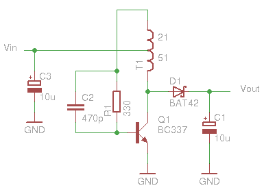
A regulator circuit is needed for this DIY project. Familiarity with electronic components, circuitry, the use of a multitester, and a soldering iron is essential. The schematic diagram provided can accept an input voltage ranging from 6 to 24 volts...
Glue stck torch
This project, developed around 2005, involves constructing a torch using a glue stick, which conveniently accommodates an AA battery within its plastic casing. To create a functional battery holder, contacts for both the positive and negative connections are necessary. The...
Help with a schematic please
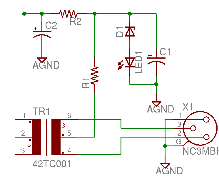
A project is underway to construct the CountryHick DI as illustrated on DIYFactory, incorporating a few minor modifications. The final design aims to be a 1U unit with four inputs.
The CountryHick DI (Direct Injection) box is a crucial tool in...

5 Minute Signal
For the past year and a half, a group based in Ann Arbor, Michigan, named GO-Tech has been formed, uniting individuals interested in creating projects using technology, such as hardware, software, metal, and wood. This initiative is referred to as...

Instrumentation circuit
The mechanical chassis prototype, as illustrated in the accompanying image, was constructed using two materials: foam and aluminum. Foam was selected for its ease of manipulation, while aluminum was chosen for its excellent strength-to-weight ratio. The prototype features a rotary...

MePADS
If you are considering building the Desert Ratt 2, it is advisable to read all the accompanying text, as it contains relevant construction details. Engaging with the comments and replies can also provide additional insights, as previous blog posts have...