


Audio-Frequency Meter Circuit
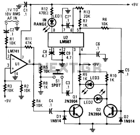
Description: This meter is unique as it does not utilize a D'Arsonval movement or digital display for frequency readings. Instead, the measured frequency is indicated on a hand-calibrated dial. Any audio signal applied to the circuit is amplified by U1, and the resulting output is divided into two paths. One path directs the output signal to the mixer, while the other path routes the signal to the input of U2 via S1, a normally open pushbutton switch. The portion of the amplifier signal sent to the mixer is applied to the base of Q1, causing it to toggle on and off at the signal frequency. In the alternate path, when S1 is pressed, a portion of the op-amp's output is directed to U2. If the signal falls within the operating frequency range of U2's internal oscillator, LED1 illuminates, and a signal is sent to the base of Q2. If the signals arriving at the mixer do not match precisely, LED2 and LED3 light up, indicating that the circuit requires fine-tuning. This is achieved by releasing S1 and adjusting R13 until LED2 and LED3 turn off. The dial setting at this point indicates the frequency of the input signal to within 1 Hz (or as accurately as the calibrated dial permits).
This unique frequency meter employs a combination of analog and digital techniques to achieve accurate frequency measurement without relying on conventional display methods. The circuit begins with an audio signal input, which is amplified by operational amplifier U1. The output from U1 is split into two distinct paths. The first path directs the signal to a mixer circuit, which is responsible for combining the input frequency with a reference frequency. The second path involves a pushbutton switch S1, which, when pressed, allows a portion of the output from U1 to be routed to the input of U2, another operational amplifier configured as an oscillator.
The toggling action of transistor Q1, driven by the signal fed from the mixer, allows for the detection of frequency variations. When the signal is within the operational range of U2's internal oscillator, it triggers LED1, indicating a successful frequency match. The system utilizes feedback from the mixer to ensure that both signals are synchronized. If they are not, LED2 and LED3 illuminate, signaling the need for adjustment.
The fine-tuning process is critical for achieving high accuracy. By releasing S1 and adjusting the variable resistor R13, the user can calibrate the circuit until the indicators (LED2 and LED3) turn off, signifying that the input signal frequency has been accurately matched to the reference frequency. The final reading is displayed on the hand-calibrated dial, providing a precise frequency measurement within a tolerance of 1 Hz. This design emphasizes user engagement through manual calibration while maintaining high accuracy and functionality in frequency measurement applications. This meter differs from the norm in that it does not use a D`Arsonval movement or digital display to give a reading of the input frequency. Instead, the measured frequency is read from a hand-cali-brated dial. Any audio signal applied to the circuit is amplified by Ul and the resulting output is divided along two paths.
In one path, the output signal is applied to the mixer; in the other path, the signal is applied to the input of U2 through SI (a normally open pushbutton switch). The portion of the amplifier signal that is fed to the mixer is applied to the base of Ql, causing it to toggle on and off at the signal frequency.
In the other path, when SI is pressed, a portion of the op amp`s output is applied to U2. If the signal is within the range of U2`s internal oscillator`s operating frequency, LED1 lights, and a signal is fed to the base of Q2. If the two signals arriving at the mixer do not match exactly, LED2 and LEDS light. That means that the circuit must be fine tuned, which is accomplished by releasing SI and fine tuning R13 until LED2 and LED3 go out.
The dial setting at that point gives the frequency of the input signal to within 1 Hz (or as close as the calibrated dial will allow).
This unique frequency meter employs a combination of analog and digital techniques to achieve accurate frequency measurement without relying on conventional display methods. The circuit begins with an audio signal input, which is amplified by operational amplifier U1. The output from U1 is split into two distinct paths. The first path directs the signal to a mixer circuit, which is responsible for combining the input frequency with a reference frequency. The second path involves a pushbutton switch S1, which, when pressed, allows a portion of the output from U1 to be routed to the input of U2, another operational amplifier configured as an oscillator.
The toggling action of transistor Q1, driven by the signal fed from the mixer, allows for the detection of frequency variations. When the signal is within the operational range of U2's internal oscillator, it triggers LED1, indicating a successful frequency match. The system utilizes feedback from the mixer to ensure that both signals are synchronized. If they are not, LED2 and LED3 illuminate, signaling the need for adjustment.
The fine-tuning process is critical for achieving high accuracy. By releasing S1 and adjusting the variable resistor R13, the user can calibrate the circuit until the indicators (LED2 and LED3) turn off, signifying that the input signal frequency has been accurately matched to the reference frequency. The final reading is displayed on the hand-calibrated dial, providing a precise frequency measurement within a tolerance of 1 Hz. This design emphasizes user engagement through manual calibration while maintaining high accuracy and functionality in frequency measurement applications. This meter differs from the norm in that it does not use a D`Arsonval movement or digital display to give a reading of the input frequency. Instead, the measured frequency is read from a hand-cali-brated dial. Any audio signal applied to the circuit is amplified by Ul and the resulting output is divided along two paths.
In one path, the output signal is applied to the mixer; in the other path, the signal is applied to the input of U2 through SI (a normally open pushbutton switch). The portion of the amplifier signal that is fed to the mixer is applied to the base of Ql, causing it to toggle on and off at the signal frequency.
In the other path, when SI is pressed, a portion of the op amp`s output is applied to U2. If the signal is within the range of U2`s internal oscillator`s operating frequency, LED1 lights, and a signal is fed to the base of Q2. If the two signals arriving at the mixer do not match exactly, LED2 and LEDS light. That means that the circuit must be fine tuned, which is accomplished by releasing SI and fine tuning R13 until LED2 and LED3 go out.
The dial setting at that point gives the frequency of the input signal to within 1 Hz (or as close as the calibrated dial will allow).

Open-Loop Peak Detector Circuit
In this open-loop design, the detector diode is D1, and a level-shifting or compensating diode is D2. Load resistor RL is connected to -5 V, and an identical bias resistor RB is used to bias the compensating diode, also connected...

Mixers
Mixers, also referred to as frequency converters, modulators, balanced modulators, and other circuit blocks, operate based on similar fundamental principles. A mixer circuit typically has two inputs from distinct signal sources. In the provided diagram, the sources are two oscillators,...
Bootstrapped Amp Current Source
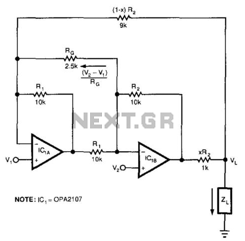
This circuit responds to the difference between Vj and V2. Rq sets the gain. Resistors XR2 and (1 - X) R2 produce the bootstrap effect. These two resistors convert the circuit's output voltage to a current. IC1 and IC2 are...

Video amplifier splitter by transistor BD137-BC547-BC557
This is a video amplifier circuit or video splitter circuit, designed to strengthen video signals. It compensates for signal loss and is...
The video amplifier circuit serves as a crucial component in video signal distribution systems, ensuring that the integrity and...

Rgb-video-amplifier
Transistors Q1 and Q2, along with their associated components, provide a low-impedance output necessary for driving the output stages. They enhance gain at high frequencies and improve video peaking for better transient response. Emitter followers Q3, Q5, and Q7 offer...
two transistor radio
This circuit is a simple one-transistor Audion type radio powered by a 1.5 V battery. It utilizes a pair of standard low-impedance headphones, wired in series to achieve a total impedance of 64 ohms. The power supply to the circuit...

Portable Mixer
A low noise circuit featuring a variable voltage gain (10 - 100) pre-set, primarily designed for high-quality microphone input, but also suitable for low-level line input. The Tone Control Module consists of a three-band (Bass, Middle, Treble) tone control circuit...

2 transistor fm voice transmitter
This circuit functions as a voice transmitter utilizing a pair of BC548 transistors. While these transistors are not specifically designed for RF applications, they still yield satisfactory performance. An ECM microphone insert from Maplin Electronics, order code FS43W, is employed....

ND838 application circuit
Figures (A), (B), (C), and (D) illustrate outputs that can directly drive transistors, thyristors, relays, CMOS circuits, and TTL circuits.
The described figures depict various output configurations capable of interfacing with different electronic components. Each output is designed to provide the...