


Basic Controls of a CRO
#CRO
#oscilloscope
#intensity control
#horizontal position
#vertical position
#voltage adjustment
#brightness control
#beam control
#instrument panel
#electronics testing

Description: The number of controls required on a panel of a Cathode Ray Oscilloscope (CRO) is essential for its proper functioning. Intensity control is provided to adjust the brightness of the spot on the screen by varying the voltage between the first and second anodes. Horizontal and vertical position controls allow for the movement of the beam to any part of the screen by applying a DC voltage to the horizontal or vertical deflection plates. Numerous other controls are present in a CRO, which will be discussed in detail. The function of the vertical deflection system is to provide an amplified signal of the appropriate level to drive the vertical deflection plates without introducing significant distortion into the system. The input sensitivity of many CROs is typically in the range of a few millivolts per division, and the voltage required to deflect the electron beam varies from approximately 100 V (peak-to-peak) to 500 V, depending on the accelerating voltage and construction of the CRT. Therefore, the vertical amplifier must provide the necessary gain from millivolt input to several hundred volts (peak-to-peak) output. Additionally, the vertical amplifier must ensure minimal distortion of the input waveform and maintain a good response across the entire frequency band being measured. The deflection plates of the CRO function as capacitor plates, and when the input signal frequency exceeds 1 MHz, the current needed for charging and discharging the capacitor formed by the deflection plates increases. Consequently, the vertical amplifier must be capable of supplying sufficient current to charge and discharge the deflection plate capacitor. It is known that electrical signals experience a delay when transmitted through electronic circuitry. In the CRO, the output voltage signal from the vertical amplifier is fed to the vertical plates of the CRT, with a portion used to trigger the time base generator circuit, which then supplies output to the horizontal deflection plates through a horizontal amplifier. This entire process, which includes generating and shaping a trigger pulse, initiating the time base generator, and amplifying the signal, takes approximately 100 ns. Therefore, the input signal to the vertical deflection plates of the CRT must be delayed by at least this duration to allow the operator to observe the leading edge of the signal waveform on the screen. To achieve this, a delay line circuit is introduced between the vertical amplifier and the CRT plates. An external signal is applied to the horizontal deflection plates through the horizontal amplifier when the sweep selector switch is in the EXT position. The horizontal amplifier, similar to the vertical amplifier, amplifies the input signal to the level required by the horizontal deflection plates of the CRT. When the function of time is to be displayed on the CRT screen, the INT position of the sweep selector switch is utilized. To understand the linear time base pattern, consider supplying an ideal saw-tooth signal voltage to the horizontal deflection plates while keeping the vertical deflection plates at zero potential. At the starting point A in time, the signal voltage is maximally negative, positioning the spot on the extreme left of the CRO screen. As time progresses to point B, the signal voltage applied to the horizontal plates becomes zero, centering the spot on the screen. When the voltage increases positively and reaches its maximum just before point C, the spot moves to the extreme right side of the screen. Immediately after point C, the next cycle of the saw-tooth voltage signal begins, causing the voltage to return to maximum negative, rapidly moving the spot back to the extreme left position from the right.
The Cathode Ray Oscilloscope (CRO) operates through a series of well-defined electronic components and systems that work together to visualize electrical signals. The intensity control adjusts the brightness of the displayed waveform by modifying the electron beam's energy, which is achieved by altering the voltage between the anodes. The horizontal and vertical position controls are critical for positioning the beam accurately on the screen, allowing users to analyze specific segments of the waveform.
The vertical deflection system is a vital component that must amplify the input signal adequately while maintaining signal integrity. The vertical amplifier's design is crucial for achieving a gain that can convert millivolt-level signals to hundreds of volts, ensuring that the signal is strong enough to deflect the beam appropriately. This amplifier must also be designed to handle high frequencies without distortion, which is particularly important when dealing with signals that exceed 1 MHz. The capacitive nature of the deflection plates necessitates that the vertical amplifier can provide sufficient current to charge and discharge the capacitance effectively.
In the CRO's signal processing chain, the delay line circuit serves a crucial role in synchronizing the displayed waveform with the input signal. By introducing a delay, the operator can observe the leading edge of the waveform, which is essential for accurate signal analysis. The horizontal amplifier, akin to the vertical amplifier, is responsible for amplifying the input signal to the necessary level for the horizontal deflection plates. The operation of the CRO is further enhanced by the sweep selector switch, which allows users to choose between displaying time-based signals or external inputs.
Overall, the CRO's design incorporates multiple controls and systems that ensure precise signal visualization, making it an invaluable tool in electronics testing and analysis.Number of controls are required to be provided on a panel of CRO to facilitate its proper functioning. Intensity control is provided for adjustment of brightness of the spot on the screen. It is accomplished by varying the voltage between the first and second anodes. The horizontal and vertical position controls are provided for moving the beam on any part of the screen. It is accomplished by applying a dc voltage to horizontal or vertical deflection plates. Similarly there are other numerous controls in a CRO, which will be discussed, in detail, here. The function of vertical deflection system is to provide an amplified signal of the proper level to drive the vertical deflection plates without introducing any appreciable distortion into the system. The input sensitivity of Many CROs is of the order of a few milli-volts per division and the voltage required for deflecting the electron beam varies from approximately 100 V (peak to peak) to 500 V depending on the accelerating voltage and the construction of the i tube.
Thus the vertical amplifier is required to provide this desired gain from milli-volt input to several hundred volt (peak to peak) output. Also the vertical amplifier should not distort the input waveform and should have good response for entire band of frequencies to be measured.
The deflection plates of CRO act as plates of a capacitor and when the input signal frequency exceeds over 1 MHz, the current required for charging and discharging of the capacitor formed by the deflection plates increases. So the vertical amplifier should be capable of supplying current enough to charge and discharge the deflection plate capacitor.
As we know that electrical signal is delayed by a certain amount of time when transmitted through an electronic circuitry. In CRO, output signal voltage of the vertical amplifier is fed to the vertical plates of CRT and some of its portion is used for triggering the time base generator circuit, whose output is supplied to the horizontal deflection plates through horizontal amplifier.
The whole process, which includes generating and shaping of a trigger pulse and starting of a time-base generator and then its amplification, takes time of the order of 100 ns or so. So the input signal of the vertical deflection platesof a CRT is to be delayed by at least the same or little more amount of time to allow the operator to see the leading edge of the signal waveform under study on the screen.
For this purpose, delay line circuit is introduced between vertical amplifier and the plates of CRT, as shown in figure. External signal is applied to horizontal deflection plates through the horizontal amplifier at the sweep selector switch in EXT position, as shown in figure.
The horizontal amplifier, similar to the vertical amplifier, increases the amplitude of the input signal to the level required by the horizontal deflection plates of CRT. When the function of time is required to be displayed on the screen of CRT, INT position of sweep selector switch is used.
Before going further we should make ourselves clear first about the linear time base pattern. Assume that we supply an ideal saw-tooth signal voltage to the horizontal deflection plates, keeping vertical deflection plates at zero potential, as shown in figure. At the starting point A in time, signal voltage is maximum but negative so the spot on the screen of CRO is at the extreme left position.
Further at point B in time, signal voltage applied to the horizontal plates is zero so the spot is in the centre position on the screen. Now when voltage increases in + ve direction and becomes maximum just before the point C, the spot on the screen is at the extreme right side of the screen.
Just after the point C, next cycle of saw-tooth voltage signal starts and again voltage becomes maximum negative so the spot goes back to the extreme left position of the screen from right position in no time
The Cathode Ray Oscilloscope (CRO) operates through a series of well-defined electronic components and systems that work together to visualize electrical signals. The intensity control adjusts the brightness of the displayed waveform by modifying the electron beam's energy, which is achieved by altering the voltage between the anodes. The horizontal and vertical position controls are critical for positioning the beam accurately on the screen, allowing users to analyze specific segments of the waveform.
The vertical deflection system is a vital component that must amplify the input signal adequately while maintaining signal integrity. The vertical amplifier's design is crucial for achieving a gain that can convert millivolt-level signals to hundreds of volts, ensuring that the signal is strong enough to deflect the beam appropriately. This amplifier must also be designed to handle high frequencies without distortion, which is particularly important when dealing with signals that exceed 1 MHz. The capacitive nature of the deflection plates necessitates that the vertical amplifier can provide sufficient current to charge and discharge the capacitance effectively.
In the CRO's signal processing chain, the delay line circuit serves a crucial role in synchronizing the displayed waveform with the input signal. By introducing a delay, the operator can observe the leading edge of the waveform, which is essential for accurate signal analysis. The horizontal amplifier, akin to the vertical amplifier, is responsible for amplifying the input signal to the necessary level for the horizontal deflection plates. The operation of the CRO is further enhanced by the sweep selector switch, which allows users to choose between displaying time-based signals or external inputs.
Overall, the CRO's design incorporates multiple controls and systems that ensure precise signal visualization, making it an invaluable tool in electronics testing and analysis.Number of controls are required to be provided on a panel of CRO to facilitate its proper functioning. Intensity control is provided for adjustment of brightness of the spot on the screen. It is accomplished by varying the voltage between the first and second anodes. The horizontal and vertical position controls are provided for moving the beam on any part of the screen. It is accomplished by applying a dc voltage to horizontal or vertical deflection plates. Similarly there are other numerous controls in a CRO, which will be discussed, in detail, here. The function of vertical deflection system is to provide an amplified signal of the proper level to drive the vertical deflection plates without introducing any appreciable distortion into the system. The input sensitivity of Many CROs is of the order of a few milli-volts per division and the voltage required for deflecting the electron beam varies from approximately 100 V (peak to peak) to 500 V depending on the accelerating voltage and the construction of the i tube.
Thus the vertical amplifier is required to provide this desired gain from milli-volt input to several hundred volt (peak to peak) output. Also the vertical amplifier should not distort the input waveform and should have good response for entire band of frequencies to be measured.
The deflection plates of CRO act as plates of a capacitor and when the input signal frequency exceeds over 1 MHz, the current required for charging and discharging of the capacitor formed by the deflection plates increases. So the vertical amplifier should be capable of supplying current enough to charge and discharge the deflection plate capacitor.
As we know that electrical signal is delayed by a certain amount of time when transmitted through an electronic circuitry. In CRO, output signal voltage of the vertical amplifier is fed to the vertical plates of CRT and some of its portion is used for triggering the time base generator circuit, whose output is supplied to the horizontal deflection plates through horizontal amplifier.
The whole process, which includes generating and shaping of a trigger pulse and starting of a time-base generator and then its amplification, takes time of the order of 100 ns or so. So the input signal of the vertical deflection platesof a CRT is to be delayed by at least the same or little more amount of time to allow the operator to see the leading edge of the signal waveform under study on the screen.
For this purpose, delay line circuit is introduced between vertical amplifier and the plates of CRT, as shown in figure. External signal is applied to horizontal deflection plates through the horizontal amplifier at the sweep selector switch in EXT position, as shown in figure.
The horizontal amplifier, similar to the vertical amplifier, increases the amplitude of the input signal to the level required by the horizontal deflection plates of CRT. When the function of time is required to be displayed on the screen of CRT, INT position of sweep selector switch is used.
Before going further we should make ourselves clear first about the linear time base pattern. Assume that we supply an ideal saw-tooth signal voltage to the horizontal deflection plates, keeping vertical deflection plates at zero potential, as shown in figure. At the starting point A in time, signal voltage is maximum but negative so the spot on the screen of CRO is at the extreme left position.
Further at point B in time, signal voltage applied to the horizontal plates is zero so the spot is in the centre position on the screen. Now when voltage increases in + ve direction and becomes maximum just before the point C, the spot on the screen is at the extreme right side of the screen.
Just after the point C, next cycle of saw-tooth voltage signal starts and again voltage becomes maximum negative so the spot goes back to the extreme left position of the screen from right position in no time
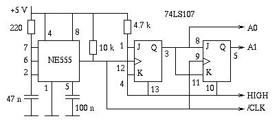
A four channel X/Y oscilloscope multiplexer
The project involves the design of a custom multiplexer for a four-channel oscilloscope, allowing for simultaneous display of multiple figures with distinct X/Y inputs. The instrument is intended to enhance the functionality of existing oscilloscopes, particularly in conjunction with analog...
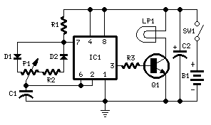
Brightness Control for small Lamps
Switch-mode driven 1.5V bulbs. This device was designed on request, to control the light intensity of four filament lamps (i.e. a ring illuminator) powered by two AA or AAA batteries, for close-up pictures with a digital camera. Obviously it can...

Two-Channel PC Based Oscilloscope USB
Portable PCs are now common, and a USB connection is a more effective solution. This document presents an oscilloscope that utilizes the USB port of a PC, operating at frequencies up to 10 kHz with an input voltage range of...

Oscilloscope AC Probe
The probe described here was designed to be used over the range of several tens of Hz to a couple MHz with currents from a few tens of milliamps to about 10 amps peak-to-peak. Formulae are given which will allow...

Mini Oscilloscope schematic
Probably the best advantage is its very small size and the fact that it can run off the power supply of the circuit being tested. Although it has a low frequency range, it can still be used for most circuits....

Resurrecting Tennis for Two a video game from 1958
Tennis for Two displayed a side-view of a tennis court on an oscilloscope screen, allowing two players to toss a ball to each other using handheld controllers. Each controller featured two controls: a button and a knob. The button enabled...

dual-trace scope switch
The switcher output connects to the single vertical input of the oscilloscope, while a sync line from one of the inputs is routed to the oscilloscope's external-sync input. The frequency response of the input amplifiers reaches 300 kHz across the...

Oscilloscope 4 Channel Adapter
The method goes by the switching method. Making it be possible to see four kinds of the input signals at the same time by switching them at the short period. In addition to the way of introducing here, there is...

Blanking Circuit for Oscilloscope
This circuit blanks the CRT starting just before retrace begins. Since the CRT sits at a -1200 volt potential, the blanking circuit must also be based at -1200 volts. Note the capacitors, C40, C41, and C43 which allow the gates...