


Components Voltage Tester Circuit Schematic
#voltage tester
#oscillator
#speaker testing
#microphone testing
#transformer testing
#low frequency
#audio pulses
#phasing check
#diagnostic tool
#circuit testing
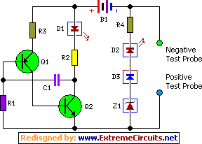
Description: This simple circuit tests speakers, microphones, transformers, and voltage. It is essentially a very low-frequency oscillator that produces extremely short pulses. The sound produced is easy to hear and helps determine the precise direction it originates from, making it ideal for checking the phasing in multiple speaker installations. It is also useful for car stereo installations and public address systems, where it can drive numerous speakers directly on a 100V or 70V line system. The signal is easily audible on a public address system, allowing for verification of each speaker while driving past. It is straightforward to check that a speaker is in phase with its neighbors by listening for the artificial center created between two identical sound sources. Transistors Q1 and Q2 oscillate when connected to loads between zero and approximately 1000 ohms. The frequency increases as the resistance of the load increases; an 8-ohm load produces about 8 Hz output, while a 100-ohm load yields about 100 Hz output, although this is only an approximation. The unit is also beneficial for checking dynamic microphones (not condenser types), headphones, transformers (both audio and mains), and resistance loads (with visual checks via the LED). The pulses generated may be too loud for some sensitive circuits, such as dynamic microphones and headphones, but the pulse duration is so short that it is virtually impossible to cause any damage; the average current flow is only a few milliamps. The circuit requires no power switch, as the oscillator operates only when the negative side of the battery is connected through the load being tested. The LED flashes with each pulse as a visual indication that the load is below approximately 1000 ohms. The circuit operates from a 3V battery pack. To use a 9V battery, the 150-ohm resistor should be changed to 47 ohms, the 1.8-ohm resistor to 5.6 ohms, and the 0.033 µF capacitor to 0.01 µF. LED2, diode D3, zener diode ZD1, and the series 220-ohm resistor form a voltage indicator that detects and indicates any voltage greater than about 10V. LED2 illuminates only if the voltage exceeds the threshold set by ZD1 and D1, which is higher than the battery voltage (3V or 9V). These components can be omitted if the device is not intended for automotive use. However, having a device that can check power wires, shorts to chassis, and speakers in a vehicle is quite convenient.
This circuit operates as a versatile testing tool for audio equipment and voltage verification. The core functionality relies on a low-frequency oscillator configuration, where transistors Q1 and Q2 act as the oscillating elements. The oscillation frequency is dependent on the load resistance, providing a range of frequencies suitable for testing different types of audio equipment. The output signal is designed to be audible, facilitating quick diagnostics of speaker phasing and performance.
In practical applications, the circuit can be utilized in various environments, including home audio systems, car audio installations, and public address systems. The ability to drive multiple speakers directly on a high-voltage line system (100V or 70V) enhances its utility in large setups, ensuring that technicians can efficiently verify the operation of numerous speakers simultaneously.
The inclusion of visual indicators, such as the LED that flashes with each pulse, adds an additional layer of functionality. This feature allows users to quickly ascertain the load status, ensuring that components are functioning as expected. The voltage indicator circuit, consisting of LED2, diode D3, and zener diode ZD1, provides a convenient means of checking for adequate voltage levels, which is particularly beneficial in automotive applications where voltage fluctuations can occur.
Overall, this circuit design is well-suited for audio technicians and engineers, providing an efficient and effective method for testing and verifying the performance of various audio components. Its simplicity and reliability make it an essential tool for anyone involved in audio equipment installation and maintenance.This simple circuit tests speakers, microphones, transformers and voltage. It`s basically a very low frequency oscillator that produces extremely short fruity` pulses. The type of sound produced is very easy to hear and to determine the precise direction it is coming from, thus making it ideal for checking the phasing in multiple speaker installat ions. It is also very useful for car stereo installations as well as public address systems where it can drive dozens of speakers directly on a 100V or 70V line system. The signal is also easy to hear on a public address system so that you can drive around a large installation with the window down and easily hear each speaker as you drive past.
It is easy to check that a speaker is in phase with its neighbours, by listening for the artificial centre created between two identical sound sources. Q1 and Q2 oscillate when connected to loads between zero and about 1000O. The frequency increases as the resistance of the load increases 8O loads produce about 8Hz output while 100O loads will produce about 100Hz output, although it is only approximate.
The unit is also useful for checking dynamic microphones (not condenser types), headphones, transformers (both audio and mains) and resistance loads (only visual checks via the LED). The pulses produced can sound too loud for some delicate circuits such as dynamic microphones and headphones, but the pulse is so short that it is virtually impossible to do any damage; the average current flow is only a few milliamps.
The circuit needs no power switch as the oscillator only operates when the negative side of the battery is connected through the load being tested. The LED flashes at each pulse as a visual indication that the load is lower than about 1000O. The circuit works from a 3V battery pack. To use a 9V battery change the 15O resistor to 47O, the 1. 8O resistor to 5. 6O and the. 033 µF capacitor to. 01 µF. LED2, diode D3, zener diode ZD1 and the series 220O resistor form a voltage indicator which is used to detect and indicate any voltage greater than about 10V.
LED2 only illuminates if the voltage rises above the threshold set by ZD1 and D1, which is more than the battery voltage (3V or 9V). These components can be omitted if the device is not going to be used for working on cars. However, it`s quite handy having a device that can check power wires, shorts to chassis and speakers in a car.
This circuit operates as a versatile testing tool for audio equipment and voltage verification. The core functionality relies on a low-frequency oscillator configuration, where transistors Q1 and Q2 act as the oscillating elements. The oscillation frequency is dependent on the load resistance, providing a range of frequencies suitable for testing different types of audio equipment. The output signal is designed to be audible, facilitating quick diagnostics of speaker phasing and performance.
In practical applications, the circuit can be utilized in various environments, including home audio systems, car audio installations, and public address systems. The ability to drive multiple speakers directly on a high-voltage line system (100V or 70V) enhances its utility in large setups, ensuring that technicians can efficiently verify the operation of numerous speakers simultaneously.
The inclusion of visual indicators, such as the LED that flashes with each pulse, adds an additional layer of functionality. This feature allows users to quickly ascertain the load status, ensuring that components are functioning as expected. The voltage indicator circuit, consisting of LED2, diode D3, and zener diode ZD1, provides a convenient means of checking for adequate voltage levels, which is particularly beneficial in automotive applications where voltage fluctuations can occur.
Overall, this circuit design is well-suited for audio technicians and engineers, providing an efficient and effective method for testing and verifying the performance of various audio components. Its simplicity and reliability make it an essential tool for anyone involved in audio equipment installation and maintenance.This simple circuit tests speakers, microphones, transformers and voltage. It`s basically a very low frequency oscillator that produces extremely short fruity` pulses. The type of sound produced is very easy to hear and to determine the precise direction it is coming from, thus making it ideal for checking the phasing in multiple speaker installat ions. It is also very useful for car stereo installations as well as public address systems where it can drive dozens of speakers directly on a 100V or 70V line system. The signal is also easy to hear on a public address system so that you can drive around a large installation with the window down and easily hear each speaker as you drive past.
It is easy to check that a speaker is in phase with its neighbours, by listening for the artificial centre created between two identical sound sources. Q1 and Q2 oscillate when connected to loads between zero and about 1000O. The frequency increases as the resistance of the load increases 8O loads produce about 8Hz output while 100O loads will produce about 100Hz output, although it is only approximate.
The unit is also useful for checking dynamic microphones (not condenser types), headphones, transformers (both audio and mains) and resistance loads (only visual checks via the LED). The pulses produced can sound too loud for some delicate circuits such as dynamic microphones and headphones, but the pulse is so short that it is virtually impossible to do any damage; the average current flow is only a few milliamps.
The circuit needs no power switch as the oscillator only operates when the negative side of the battery is connected through the load being tested. The LED flashes at each pulse as a visual indication that the load is lower than about 1000O. The circuit works from a 3V battery pack. To use a 9V battery change the 15O resistor to 47O, the 1. 8O resistor to 5. 6O and the. 033 µF capacitor to. 01 µF. LED2, diode D3, zener diode ZD1 and the series 220O resistor form a voltage indicator which is used to detect and indicate any voltage greater than about 10V.
LED2 only illuminates if the voltage rises above the threshold set by ZD1 and D1, which is more than the battery voltage (3V or 9V). These components can be omitted if the device is not going to be used for working on cars. However, it`s quite handy having a device that can check power wires, shorts to chassis and speakers in a car.

Electronic pests killing lamp circuit diagram 4
The electronic pest-killing lamp circuit comprises an oscillator, control circuit, high voltage generator, LED indicator circuit, and power supply circuit. The schematic diagram illustrates these components. The oscillator circuit includes a time-base integrated circuit (IC), resistors R5 to R7, diodes...

The Ecology of the Oscillator Transmitter
An oscillator-only transmitter appears to be the simplest way to access the radio airwaves; however, it presents several challenges as part of a transmitting and receiving station. The issue of finding an adequate crystal-controlled transmitter for newcomers wishing to operate...

Metal detector circuit diagram 3
The metal detector consists of a probe oscillator, a reference oscillator, an audio amplifier, and various other components, as illustrated in the schematic. The probe oscillator is made up of transistors V1 and V2, a detection coil L1, a capacitor...
oscillator
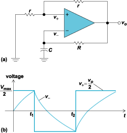
An oscillator is an electronic circuit that converts energy from a direct-current source into a periodically varying electric output.
An oscillator is a fundamental component in various electronic systems, serving the purpose of generating oscillating signals, typically in the form of...

Metal detector circuit diagram 8
The metal detector circuit consists of a probe oscillator, a PLL (phase-locked loop) circuit, and an audio alarm circuit. The probe oscillator includes a detection coil (L), transistor (V1), and several resistors (R1 to R3) and capacitors (C1 to C5)....

VHF/UHF TV Modulator
A simple oscillator generates a frequency in the VHF or UHF range. This oscillator is modulated with a video signal, and the resulting modulated carrier wave is transmitted to the TV set's aerial input through a cable. The final step...
Last-cycle-completing-gated-oscillator
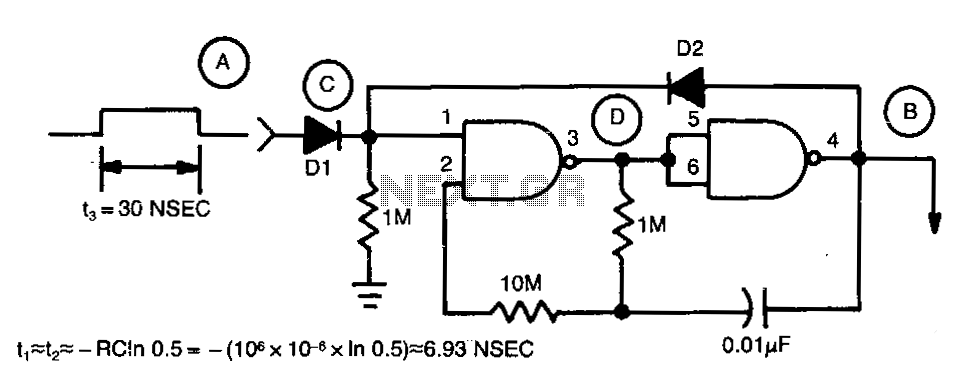
Regenerative feedback at capacitor C allows the oscillator to complete its timing cycle instead of shutting off immediately. The integrated circuit (IC) used was a CD4011AE, although an equivalent IC will also function.
The described circuit utilizes regenerative feedback to enhance...

why doesnt this circuit oscillate
The buba oscillator initially failed to oscillate. The first step is to check the fundamental components, as minor errors in the values of capacitors, resistors, and inductors can significantly impact performance. It is advisable to measure component values with a...

Oscillator-clock generator
This self-starting fixed frequency oscillator circuit provides excellent frequency stability. R1 and C1 form the frequency-determining network, while R2 supplies regenerative feedback. Diode D1 improves stability by compensating for the difference between Voh and Vsupply. In applications requiring a precision...