


Digital Lux Meter
#lux meter
#photo diode
#I-V converter
#microcontroller
#op-amp
#9V battery
#light measurement
#sensor
#feedback resistor

Description: Photo diode outputs light current that is well proportional to input light power when it is used in short mode. In this lux meter, the output current is converted to voltage with an I-V converter, it is captured by a microcontroller and displayed in terms of lux. The op-amp U1 in the Circuit Diagram acts as the I-V conversion circuit and its conversion rate becomes 50mV/µA according to a feedback resistor R5. The capacitor C5 is to gain correction, it cancels Ct of the photo diode (approx. 200 pF). In this case, larger capacitance may be good rather than 220 pF because high frequency signal is not needed. The lux meter is powered by a 9V battery. To minimize battery space, it is made contact with two pieces of springs made of nickel plated copper phosphorus alloy instead of a battery snap. However, it is not an anti-reverse insertion structure; any protection circuit is needed. More: Q1 is the reverse insertion protector which has no voltage loss like a series diode. Q2 is a main switch that constructs a power hold circuit with Q3 and Q4. The main function of the firmware is only capturing sensor output with an A-D converter and displaying it on the LED display. The built-in A-D converter of AVR has 10-bit resolution but it is slightly insufficient for an industrial measurement system. The A-D converter unit has a gain amplifier which can be inserted between the multiplexer and the A-D converter. This enables improving resolution by changing the input gain automatically. To implement this function, capture input at a gain of 20; if overflow occurs, capture it again at a gain of 1. As a result, the resolution can be improved at small input regions that have lower relative resolution. Maximum light input is approximately 30,000 lux due to the A-D input range of 0 to 2.56 V. Any reference light source will not be available in most cases. Calibration of the lux meter must depend solely on the data sheet. The short current is Isc = 0.16µA/100lux, according to the S1087 data sheet. It becomes 2µA at 1250 lux. When -100 mV is applied to the test pin (TP1), it is equivalent to 1250 lux at the photo diode, and the I-V converter will output 100 mV. To perform calibration, tie ISP pins via several kΩ resistors, turn on power, and calibrate to the reference input. The low range is calibrated when SCK-GND and -100 mV on TP1, while the high range is calibrated when MOSI-GND and -1 V on TP1. Of course, the photo diode must be masked during calibration, or the result will be invalid. When the lux meter is housed in any clear case including the light sensor, additional calibration is required to consider decrease due to the case. When the cover is closed and lux decreases by 10%, recalibrate again with 10% decreased voltages. The result from the A-D converter is multiplied by a calibration value to display on the LED in terms of lux. The LED will blink in low-battery conditions.
The lux meter circuit primarily utilizes a photodiode that generates a current proportional to the incident light intensity. This current is fed into an operational amplifier (U1), configured as an I-V converter. The feedback resistor (R5) sets the conversion factor to 50 mV/µA, allowing for precise voltage output corresponding to the light intensity. Capacitor C5 is strategically placed to correct gain and stabilize the circuit by compensating for the photodiode's capacitance, which is approximately 200 pF. A larger capacitor may be beneficial in this application to ensure stability at lower frequencies, as high-frequency response is not critical.
Power is supplied by a 9V battery, with innovative contact achieved through nickel-plated copper-phosphorus alloy springs, which reduces space compared to traditional battery snaps. However, the design lacks reverse polarity protection, necessitating the inclusion of a protection circuit. The transistor Q1 serves this function, allowing current flow without introducing significant voltage drop, unlike conventional series diodes.
The microcontroller captures the output from the I-V converter using an integrated A-D converter, which has a resolution of 10 bits. Although this is generally adequate, it may fall short for more demanding industrial applications. To enhance measurement accuracy, a gain amplifier can be employed between the multiplexer and the A-D converter, allowing for automatic gain adjustments. This dual-gain approach captures inputs first at a higher gain of 20 and, in the event of overflow, at a standard gain of 1, which significantly improves resolution for lower light levels.
Calibration is a critical aspect of the lux meter's accuracy. The short-circuit current generated by the photodiode is specified in the S1087 datasheet, providing a baseline for calibration. The calibration process involves applying known voltages to the test pin (TP1) and adjusting the system accordingly. The calibration procedure also accounts for potential discrepancies introduced by housing the sensor in a protective case, necessitating adjustments based on the observed light attenuation.
Finally, the output from the A-D converter is scaled by a calibration factor to present the lux value on an LED display. The system includes a low-battery indicator, ensuring that users are aware of power levels to maintain measurement reliability.Photo diode outputs light current that is well proportional to input light power when it is used in short mode. In this lux meter, the output current is converted to voltage with an I-V converter, it is captured by a micrcontroller and displayed it in term of lux.
The ppamp U1 in the Circuit Diagram acts as the I-V conversion circuit and its conversion rate becomes 50mV/µA according to a feedback register R5. The capacitor C5 is to gain correction, it cancels Ct of the photo diode (approx. 200 pF). In this case, larger capacitance may be good rather than 220 pF because high frequency signal is not needed.
The lux meter is powered by a 9V battery. To minimize battery space, it is made contact with two piece of springs made of nickel plated copper phosphorus alloy instead of a battery snap. However it is not anti-reverse insertion structure, any protection circuit is needed. Q1 is the reverse insertion protector which has not voltage loss like series diode. Q2 is a main swich constructs power hold circuit with Q3 and Q4. Main function of the firmware is only captureing sensor output with A-D converter and display it to the LED display. The built-in A-D converter of AVR has 10 bit resolution but it is slightly insufficient for industrial measurement system.
The A-D converter unit has a gain amplifier which can be inserted between multiplexer and A-D converter. This enables to improve resolution by changing the input gain automatically. To implement this funciton, capture input in gain of 20, if overflow occured, capture it again in gain of 1.
As a result, can improve resolution at small input resion that lower relative resolution. Maximum light input is approx. 30000 lux due to A-D input raige of 0 to 2.56 V. Any reference light source will not be available in most case. We have to depend on only the data sheet to calibrate lux meter. The short current is Isc = 0.16µA/100lux, according to S1087 data sheet. It becomes 2µA at 1250 lux. When -100 mV is applied to test pin (TP1), it is equivalent to 1250 lux at photo diode, and I-V converter will output 100 mV. To perform calibration, tie ISP pins via a several k? resister, turn on power, and will be calibrated to the reference input. Low range is calibrated when SCK-GND and -100 mV on TP1, High range is calibrated when MOSI-GND and -1 V on TP1.
Ofcource photo diode must be masked while calibration, or the reslut will be invalid. When lux meter is housed into any clear case including light sensor, additional calibration is required to consider decrease due to case. When closed cover and lux decreased 10%, calibrate again with 10% decreased voltages. The result from A-D comverter is multiplied by a calibration value to LED display in term of lux. The LED will blink in low-battery condition.
The lux meter circuit primarily utilizes a photodiode that generates a current proportional to the incident light intensity. This current is fed into an operational amplifier (U1), configured as an I-V converter. The feedback resistor (R5) sets the conversion factor to 50 mV/µA, allowing for precise voltage output corresponding to the light intensity. Capacitor C5 is strategically placed to correct gain and stabilize the circuit by compensating for the photodiode's capacitance, which is approximately 200 pF. A larger capacitor may be beneficial in this application to ensure stability at lower frequencies, as high-frequency response is not critical.
Power is supplied by a 9V battery, with innovative contact achieved through nickel-plated copper-phosphorus alloy springs, which reduces space compared to traditional battery snaps. However, the design lacks reverse polarity protection, necessitating the inclusion of a protection circuit. The transistor Q1 serves this function, allowing current flow without introducing significant voltage drop, unlike conventional series diodes.
The microcontroller captures the output from the I-V converter using an integrated A-D converter, which has a resolution of 10 bits. Although this is generally adequate, it may fall short for more demanding industrial applications. To enhance measurement accuracy, a gain amplifier can be employed between the multiplexer and the A-D converter, allowing for automatic gain adjustments. This dual-gain approach captures inputs first at a higher gain of 20 and, in the event of overflow, at a standard gain of 1, which significantly improves resolution for lower light levels.
Calibration is a critical aspect of the lux meter's accuracy. The short-circuit current generated by the photodiode is specified in the S1087 datasheet, providing a baseline for calibration. The calibration process involves applying known voltages to the test pin (TP1) and adjusting the system accordingly. The calibration procedure also accounts for potential discrepancies introduced by housing the sensor in a protective case, necessitating adjustments based on the observed light attenuation.
Finally, the output from the A-D converter is scaled by a calibration factor to present the lux value on an LED display. The system includes a low-battery indicator, ensuring that users are aware of power levels to maintain measurement reliability.Photo diode outputs light current that is well proportional to input light power when it is used in short mode. In this lux meter, the output current is converted to voltage with an I-V converter, it is captured by a micrcontroller and displayed it in term of lux.
The ppamp U1 in the Circuit Diagram acts as the I-V conversion circuit and its conversion rate becomes 50mV/µA according to a feedback register R5. The capacitor C5 is to gain correction, it cancels Ct of the photo diode (approx. 200 pF). In this case, larger capacitance may be good rather than 220 pF because high frequency signal is not needed.
The lux meter is powered by a 9V battery. To minimize battery space, it is made contact with two piece of springs made of nickel plated copper phosphorus alloy instead of a battery snap. However it is not anti-reverse insertion structure, any protection circuit is needed. Q1 is the reverse insertion protector which has not voltage loss like series diode. Q2 is a main swich constructs power hold circuit with Q3 and Q4. Main function of the firmware is only captureing sensor output with A-D converter and display it to the LED display. The built-in A-D converter of AVR has 10 bit resolution but it is slightly insufficient for industrial measurement system.
The A-D converter unit has a gain amplifier which can be inserted between multiplexer and A-D converter. This enables to improve resolution by changing the input gain automatically. To implement this funciton, capture input in gain of 20, if overflow occured, capture it again in gain of 1.
As a result, can improve resolution at small input resion that lower relative resolution. Maximum light input is approx. 30000 lux due to A-D input raige of 0 to 2.56 V. Any reference light source will not be available in most case. We have to depend on only the data sheet to calibrate lux meter. The short current is Isc = 0.16µA/100lux, according to S1087 data sheet. It becomes 2µA at 1250 lux. When -100 mV is applied to test pin (TP1), it is equivalent to 1250 lux at photo diode, and I-V converter will output 100 mV. To perform calibration, tie ISP pins via a several k? resister, turn on power, and will be calibrated to the reference input. Low range is calibrated when SCK-GND and -100 mV on TP1, High range is calibrated when MOSI-GND and -1 V on TP1.
Ofcource photo diode must be masked while calibration, or the reslut will be invalid. When lux meter is housed into any clear case including light sensor, additional calibration is required to consider decrease due to case. When closed cover and lux decreased 10%, calibrate again with 10% decreased voltages. The result from A-D comverter is multiplied by a calibration value to LED display in term of lux. The LED will blink in low-battery condition.

Cipher scheme of the module of infrared remote-control between two parties of intellectual family
This system is a control system based on a single-chip computer that allows for remote operation of lighting. The scheme primarily addresses the transmission and reception of signals, as well as program manipulation of various signals once they are processed...

Home Built Laser Projector
This document outlines the servo amplifier and its circuit diagram. It describes a straightforward operational amplifier circuit that integrates both a power amplifier and a small signal amplifier on the same board. Care must be taken to avoid unintended coupling...

Differential-to-single-ended-voltage-amplifier
This circuit utilizes a CA5470 quad microprocessor BiMOS-E operational amplifier. Amplifiers A1 and A2 are configured as a cross-coupled differential input and differential output preamplifier stage, while A3 is responsible for input guard-banding. Additionally, amplifier A4 converts the differential outputs...

Experimental I/O board for microcontrollers
For beginners experiencing similar challenges, a general-purpose I/O board is recommended to minimize prototyping time and maximize space on the breadboard for projects. The construction of this board is straightforward. Basic I/O devices can be soldered onto a general-purpose perforated...
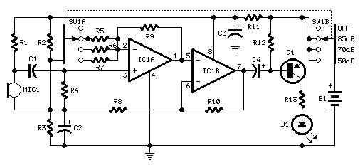
Room Noise Detector Schematic Circuit
This circuit is designed to signal the exceeding of a fixed threshold in room noise through a flashing LED. Three fixed levels are selectable: 50, 70, and 85 dB. Two operational amplifiers provide the necessary gain for sounds captured by...

Positive Pulse Pulse Stretcher
A simple pulse stretcher built with two sections of an operational amplifier uses a voltage follower U1A to drive D1 and C2. C2 charges to the peak value of the pulse voltage. Resistors R3 and R4 determine the discharge time...

microcontroller Generate a reset signal from a falling edge trigger
The microcontroller design features the microcontroller (MCU) in hibernation mode, which can only be awakened by a pulse (high-low-high) signal on the reset pin (active low). An accelerometer or an external real-time clock (RTC) serves as the wake-up source. The...

mosfet Turning a microcontroller on with a flip flop
The objective is to control the power to a load, specifically an 8051-based microcontroller (uC), using two switches. When the uC is powered on, it sets the PWR pin high. Upon pressing the switches again, pin 4 of the flip-flop...

Sine to rectangular wave conversion circuit
The optimal operational amplifier circuit used to convert a sine waveform into a rectangular waveform is the Schmitt trigger circuit.
The Schmitt trigger circuit is a vital component in signal processing, particularly for converting analog signals into digital signals. It utilizes...