


Electrolytic Tester

Description: Firstly, we will describe the add-on version for the 5x7 Display as this is the cheapest version and, quite frankly, it only deserves a few dollars as a piece of test equipment. It's all the rage to have an Electrolytic Tester for servicing equipment and yet I have serviced over 36,000 appliances without one. Possibly it took me a long time to realize electrolytics have the capability of drying out because old-style electros were inherently very reliable and, of course, they were not old when the equipment was being repaired. More: Now . . . it's not impossible to live without one. All you have to do is replace all the electros in a faulty piece of equipment, then turn it on and see the results. Charles had a stereo amplifier in for repair recently and he started at one end.
The add-on version for the 5x7 Display is designed to provide a cost-effective solution for testing and servicing electronic equipment, particularly in applications where budget constraints are significant. This version is particularly suited for hobbyists and technicians who require basic functionality without the need for advanced features found in more expensive testers.
The schematic for the add-on version typically includes a microcontroller interfaced with a 5x7 LED matrix display. The microcontroller serves as the central processing unit, executing the necessary logic to read input values from capacitors under test and display the results on the matrix. The 5x7 display is composed of 35 individual LEDs arranged in a grid format, allowing for the representation of alphanumeric characters and simple graphics.
Key components of the circuit include:
1. **Microcontroller**: A low-power microcontroller, such as an ATmega series, is selected for its versatility and ease of programming. It manages input/output operations and controls the display.
2. **LED Matrix Display**: The 5x7 LED matrix is driven by the microcontroller using a combination of direct pin control and multiplexing techniques to minimize the number of required pins.
3. **Capacitor Testing Circuit**: A simple RC circuit may be implemented to measure the capacitance and equivalent series resistance (ESR) of electrolytic capacitors. The microcontroller can measure the time constant of the RC circuit to determine capacitance values.
4. **Power Supply**: A regulated power supply circuit is included to ensure stable operation of the microcontroller and display. This may consist of a voltage regulator and filtering capacitors to reduce noise.
5. **User Interface**: Basic buttons may be included for user input, allowing the technician to select different modes of operation or initiate tests.
6. **Output Indicators**: Additional LEDs can be included to provide visual feedback on the status of the testing process, indicating pass/fail results.
Overall, the add-on version for the 5x7 Display is a practical tool for technicians who need a straightforward and economical method for testing electrolytic capacitors and other components in electronic devices. The design emphasizes simplicity and functionality, making it accessible for users with varying levels of experience in electronics repair.Firstly, we will describe the "add-on" version for the 5x7 Display as this is the cheapest version and, quite frankly, it only deserves a few dollars as a piece of test equipment. It`s "all the rage" to have an Electrolytic Tester for servicing equipment and yet I have serviced over 36,000 appliances without one.
Possibly it took me a long time to realise electrolytics have the capability of drying out because old-style electros were inherently very reliable and, of-course, they were not old when the equipment was being repaired. Now . . . it`s not impossible to live without one. All you have to do is replace all the electros in a faulty piece of equipment, then turn it on and see the results. Charles had a stereo amplifier in for repair recently and he started at one end
The add-on version for the 5x7 Display is designed to provide a cost-effective solution for testing and servicing electronic equipment, particularly in applications where budget constraints are significant. This version is particularly suited for hobbyists and technicians who require basic functionality without the need for advanced features found in more expensive testers.
The schematic for the add-on version typically includes a microcontroller interfaced with a 5x7 LED matrix display. The microcontroller serves as the central processing unit, executing the necessary logic to read input values from capacitors under test and display the results on the matrix. The 5x7 display is composed of 35 individual LEDs arranged in a grid format, allowing for the representation of alphanumeric characters and simple graphics.
Key components of the circuit include:
1. **Microcontroller**: A low-power microcontroller, such as an ATmega series, is selected for its versatility and ease of programming. It manages input/output operations and controls the display.
2. **LED Matrix Display**: The 5x7 LED matrix is driven by the microcontroller using a combination of direct pin control and multiplexing techniques to minimize the number of required pins.
3. **Capacitor Testing Circuit**: A simple RC circuit may be implemented to measure the capacitance and equivalent series resistance (ESR) of electrolytic capacitors. The microcontroller can measure the time constant of the RC circuit to determine capacitance values.
4. **Power Supply**: A regulated power supply circuit is included to ensure stable operation of the microcontroller and display. This may consist of a voltage regulator and filtering capacitors to reduce noise.
5. **User Interface**: Basic buttons may be included for user input, allowing the technician to select different modes of operation or initiate tests.
6. **Output Indicators**: Additional LEDs can be included to provide visual feedback on the status of the testing process, indicating pass/fail results.
Overall, the add-on version for the 5x7 Display is a practical tool for technicians who need a straightforward and economical method for testing electrolytic capacitors and other components in electronic devices. The design emphasizes simplicity and functionality, making it accessible for users with varying levels of experience in electronics repair.Firstly, we will describe the "add-on" version for the 5x7 Display as this is the cheapest version and, quite frankly, it only deserves a few dollars as a piece of test equipment. It`s "all the rage" to have an Electrolytic Tester for servicing equipment and yet I have serviced over 36,000 appliances without one.
Possibly it took me a long time to realise electrolytics have the capability of drying out because old-style electros were inherently very reliable and, of-course, they were not old when the equipment was being repaired. Now . . . it`s not impossible to live without one. All you have to do is replace all the electros in a faulty piece of equipment, then turn it on and see the results. Charles had a stereo amplifier in for repair recently and he started at one end

adj pwr
The design incorporates a universal capacitor mounting and spacing feature, enabling compatibility with various capacitor types. It includes a mounting pattern suitable for TO-200 or TO-218/247 packages, specifically for the pass transistor and the transistor utilized in the current limit...
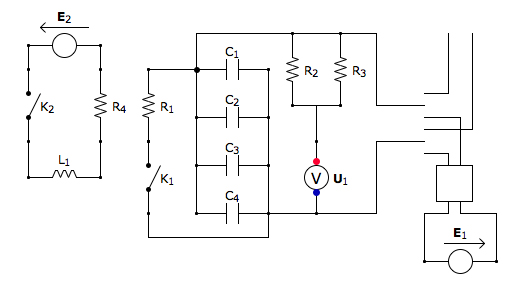
Capacitor Box Circuit
This is the discharging circuit. The red lines indicate the flow of energy from the capacitors to the terminals when the switch is in the upward position. The circuit is complete due to the connection of the terminals by Ni-Chrome...

Help me Understand this Circuit Schematic
The roles of capacitors C1, C4, and C5 in a circuit may not be immediately clear. Capacitors on the power rail help to smooth out the signal by reducing current ripple, which can be observed using an oscilloscope. Resistors R6...

The second phase alarm circuit
A capacitor C1 and resistors R1-R3 form a negative sequence voltage filtration device. The resistors and capacitors must meet the following requirements: R1, R2, R3 = 5.5/C1 (KN). The relationship between the resistance and capacitance values is arbitrary. Capacitor selection...
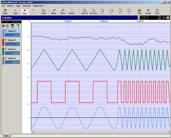
RealView 2.0
RealView is a measurement application, which records and plots measured values from analogue hardware devices in real-time. Several curves can be plotted into a single diagram. Several diagrams can be arranged on one or more pages if necessary. Plot options...

Electronics Projects Circuits
Over 1400 top electronics projects and electronic circuits with photos, datasheets, and easy-to-read schematics, along with explanations of how they work and how to build them.
The collection comprises a vast array of electronics projects suitable for enthusiasts and professionals alike....
own capacitor
The capacitor is composed of two sheets of aluminum foil. It is essential to keep the foil within the plastic packets and connect them using crocodile clips, ensuring that the clips do not touch each other. The initial frequency of...

ELF MONITOR
The capacitor instrument is not intended for measuring the capacitance of capacitors; rather, it is designed to identify whether a capacitor is functional or defective, as well as to detect short circuits or open circuits. This functionality provides reliable quality...

How the capacitor works (in a debouncing circuit)
Understand why the LED does not light up, as the capacitor appears to be bypassing the switch. When the capacitor is fully charged, it does not conduct electricity. Although the individual is a beginner, after 20 hours of studying various...