


Energy Consumption Monitor Circuit
#energy monitor
#power consumption
#voltage converter
#bargraph display
#pulse converter
#counter module
#real power measurement
#load monitoring
#instrumentation

Description: The ECM circuit comprises four sections, as illustrated in the block diagram. A power converter generates a voltage that correlates with the actual real power consumed by the load. This voltage supplies both a bar graph and a voltage-to-pulse converter. The bar graph provides an approximate indication of the power used, while the voltage-to-pulse converter generates a pulse whose frequency is proportional to the power consumption. This pulse activates the counter module, which displays the cost of powering the monitored load.
The ECM circuit is designed to monitor and display power consumption in a clear and efficient manner. The power converter is a critical component that transforms the electrical characteristics of the load into a usable voltage signal. This voltage is typically derived from a current transformer or a shunt resistor, ensuring accurate representation of the real power consumed.
The bar graph serves as a visual representation of power usage, allowing users to quickly assess the load's energy consumption without needing to interpret numerical data. It is typically composed of a series of LEDs or a liquid crystal display (LCD) that lights up in proportion to the power consumed.
The voltage-to-pulse converter is essential for translating the analog voltage signal into a digital format that can be processed by the counter module. This converter operates by generating a pulse train where the frequency of the pulses is directly proportional to the input voltage, effectively encoding the power consumption into a frequency signal.
The counter module, often integrated with a microcontroller or a digital signal processor, counts the incoming pulses over a defined time interval. This count is then converted into a cost estimate based on predefined rates for energy consumption. The display can be a simple numeric readout or a more complex graphical interface, depending on the design requirements.
In summary, the ECM circuit provides a comprehensive solution for monitoring power consumption, converting it into useful visual and numerical data, and facilitating cost analysis for energy usage in various applications. Its modular design allows for flexibility and scalability in different environments, making it suitable for residential, commercial, or industrial applications. The ECM circuit consists of four sections, as shown in the block diagram. A power converter generates a voltage that is proportional to the true of real power consumed by the load. That voltage feeds both a bargraph and a voltage-to-pulse converter. The bargraph gives an approximate indication of the amount of power used, and the voltage-to-pulse converter produces a pulse whose frequency is proportional to the power.
The pulse triggers the counter module, which displays the cost of powering the monitored load.
The ECM circuit is designed to monitor and display power consumption in a clear and efficient manner. The power converter is a critical component that transforms the electrical characteristics of the load into a usable voltage signal. This voltage is typically derived from a current transformer or a shunt resistor, ensuring accurate representation of the real power consumed.
The bar graph serves as a visual representation of power usage, allowing users to quickly assess the load's energy consumption without needing to interpret numerical data. It is typically composed of a series of LEDs or a liquid crystal display (LCD) that lights up in proportion to the power consumed.
The voltage-to-pulse converter is essential for translating the analog voltage signal into a digital format that can be processed by the counter module. This converter operates by generating a pulse train where the frequency of the pulses is directly proportional to the input voltage, effectively encoding the power consumption into a frequency signal.
The counter module, often integrated with a microcontroller or a digital signal processor, counts the incoming pulses over a defined time interval. This count is then converted into a cost estimate based on predefined rates for energy consumption. The display can be a simple numeric readout or a more complex graphical interface, depending on the design requirements.
In summary, the ECM circuit provides a comprehensive solution for monitoring power consumption, converting it into useful visual and numerical data, and facilitating cost analysis for energy usage in various applications. Its modular design allows for flexibility and scalability in different environments, making it suitable for residential, commercial, or industrial applications. The ECM circuit consists of four sections, as shown in the block diagram. A power converter generates a voltage that is proportional to the true of real power consumed by the load. That voltage feeds both a bargraph and a voltage-to-pulse converter. The bargraph gives an approximate indication of the amount of power used, and the voltage-to-pulse converter produces a pulse whose frequency is proportional to the power.
The pulse triggers the counter module, which displays the cost of powering the monitored load.

6V to 12V Converter
This inverter circuit can provide up to 800mA of 12V power from a 6V supply. For example, you could run 12V car accessories in a 6V car. The circuit is simple, about 75% efficient and quite useful. By changing just...
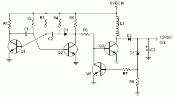
6vdc to 12vdc converter circuit
Various values of D3 can be utilized to achieve different output voltages ranging from approximately 0.6V to around 30V. It is important to note that at elevated voltages, the circuit's performance may diminish, potentially resulting in lower current output. Additionally,...

12v to +5V, -12V, +12V, +24V adaptor
Many times we needed a variety of voltages, from a battery 12V. With the circuit, we can take voltages smaller or bigger, positive or negative, from a battery 12V. The idea is based in oscillator roughly 7KHZ, round the R1,...

12v to 3v converter
This document presents a straightforward and practical schematic for a 12V to 3V converter circuit. The output current of the circuit is approximately 1A.
The 12V to 3V converter circuit is typically designed using a linear voltage regulator or a buck...

Voltage Converter 3V to 5V using MAX660
Voltage converter circuit diagram for converting 3 volts to 5 volts using CMOS monolithic ICs MAX660 and MAX667, which functions as a positive voltage regulator.
The voltage converter circuit utilizes the MAX660 and MAX667 integrated circuits to step up a 3-volt...

Inductorless 3-5 Volts Converter
By configuring a comparator and a transistor to control the oscillator in a charge pump circuit, it is possible to generate a regulated output of virtually any desired value. Charge pump integrated circuits (ICs) can either invert or double an...

12V to 220V converter circuit
This DIY 12V to 220V voltage converter is built with a CMOS 4047, which serves as the main component for transforming 12V DC into 220V AC. The 4047 operates as an astable multivibrator, generating a symmetrical rectangular signal at pins...

3V to 5V Converter Circuit
There are several methods to convert an AC voltage from a wall receptacle into the DC voltage required by a microcontroller. Traditionally, this has been accomplished using various types of power supply circuits.
To convert AC voltage to DC voltage effectively,...

Adjustable Voltage Step-down Converter
The LinkSwitch-XT LNK363DN-based flyback power supply generates a single isolated DC output voltage from an input voltage range of 90 VAC to 264 VAC. The power supply delivers an output of 5 V at 550 mA (2.75 W) in a...