


Fet-probe
#FET probe
#high impedance
#frequency response
#UHF transistor
#2N5246
#2N3704
#measurement
#instrumentation
#electronics testing

Description: This FET probe features an input impedance of 10 MΩ, which is shunted by 8 pF. Removing the protective diodes reduces this impedance to approximately 4 pF. The frequency response of the probe ranges from DC to 20 MHz (-1 dB), although operation at higher frequencies can be achieved through optimized design and the use of a UHF-type transistor. A zero DC offset at the output is accomplished by selecting a combination of a 2N5246 and a source resistor that ensures a gate-source bias equivalent to the VBE of the 2N3704 at around 0 V. At medium frequencies, the probe can be used unterminated for near-unity gain; for optimal impedance conversion and high-frequency response, the cable must be terminated into 50 Ω. When properly terminated, the voltage gain is precisely 0.5X.
The FET probe described is designed for high-impedance applications, making it suitable for measuring signals without significantly loading the circuit under test. The input impedance of 10 MΩ combined with a shunt capacitance of 8 pF allows for effective signal acquisition while minimizing distortion. The reduction of impedance to 4 pF by eliminating protective diodes enhances the probe's performance at higher frequencies, making it particularly useful for applications where fast transient response is critical.
The frequency response of the probe, extending from DC to 20 MHz, indicates its versatility in various electronic testing scenarios. The ability to achieve higher frequency performance through optimized construction, particularly with a UHF-type transistor, suggests that the design can accommodate a range of high-frequency applications, potentially reaching into the UHF spectrum.
Achieving a zero DC offset is crucial for accurate measurements, and the specified configuration using a 2N5246 and a source resistor to match the VBE of the 2N3704 ensures that the output remains stable at around 0 V. This feature is particularly beneficial in precision measurement environments where DC offsets can lead to erroneous readings.
The probe's capability to operate unterminated at medium frequencies for near-unity gain simplifies usage in many scenarios, allowing for direct connection to test points without additional termination. However, for applications requiring optimal performance, particularly at high frequencies, terminating the cable into 50 Ω is essential. This termination not only enhances the impedance matching but also ensures that the voltage gain is accurately maintained at 0.5X, providing reliable and consistent measurement results.
In summary, the design of this FET probe integrates high input impedance, low capacitance, and effective frequency response characteristics, making it a valuable tool for engineers and technicians engaged in high-frequency electronic testing and analysis.This FET probe has an input impedance of 10 M!J shunted by 8 pF. Eliminating the protective diodes reduces this impedance to about 4 pF. The frequency response of the probe extends from de to 20 MHz ( -1 dB), although higher frequency operation is possible through optimized construction and use of a UHF-type transistor. Zero de offset at the output is achieved by selecting a combination of a 2N5246 and source resistor that yields a gate-source bias equal to the V8E of the 2N3704 at approximately 0 V.
At medium frequencies, the probe can be used unterminated for near-unity gain; for optimum impedance converter probe high-frequency response, the cable must be terminated into 50 !J. The voltage gain, when properly terminated, is precisely 0.5 X.
The FET probe described is designed for high-impedance applications, making it suitable for measuring signals without significantly loading the circuit under test. The input impedance of 10 MΩ combined with a shunt capacitance of 8 pF allows for effective signal acquisition while minimizing distortion. The reduction of impedance to 4 pF by eliminating protective diodes enhances the probe's performance at higher frequencies, making it particularly useful for applications where fast transient response is critical.
The frequency response of the probe, extending from DC to 20 MHz, indicates its versatility in various electronic testing scenarios. The ability to achieve higher frequency performance through optimized construction, particularly with a UHF-type transistor, suggests that the design can accommodate a range of high-frequency applications, potentially reaching into the UHF spectrum.
Achieving a zero DC offset is crucial for accurate measurements, and the specified configuration using a 2N5246 and a source resistor to match the VBE of the 2N3704 ensures that the output remains stable at around 0 V. This feature is particularly beneficial in precision measurement environments where DC offsets can lead to erroneous readings.
The probe's capability to operate unterminated at medium frequencies for near-unity gain simplifies usage in many scenarios, allowing for direct connection to test points without additional termination. However, for applications requiring optimal performance, particularly at high frequencies, terminating the cable into 50 Ω is essential. This termination not only enhances the impedance matching but also ensures that the voltage gain is accurately maintained at 0.5X, providing reliable and consistent measurement results.
In summary, the design of this FET probe integrates high input impedance, low capacitance, and effective frequency response characteristics, making it a valuable tool for engineers and technicians engaged in high-frequency electronic testing and analysis.This FET probe has an input impedance of 10 M!J shunted by 8 pF. Eliminating the protective diodes reduces this impedance to about 4 pF. The frequency response of the probe extends from de to 20 MHz ( -1 dB), although higher frequency operation is possible through optimized construction and use of a UHF-type transistor. Zero de offset at the output is achieved by selecting a combination of a 2N5246 and source resistor that yields a gate-source bias equal to the V8E of the 2N3704 at approximately 0 V.
At medium frequencies, the probe can be used unterminated for near-unity gain; for optimum impedance converter probe high-frequency response, the cable must be terminated into 50 !J. The voltage gain, when properly terminated, is precisely 0.5 X.

Blanket internal measurement circuit disconnection
The internal disconnection circuit for a blanket operates on the principle of induction. It includes a wire approximately 2 cm in length that senses the proximity of a charged mains power source. When the sensing wire is close to the...
RealView 2.0
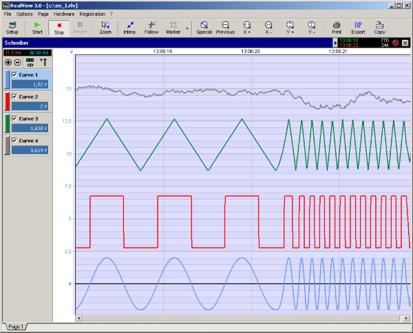
RealView is a measurement application, which records and plots measured values from analogue hardware devices in real-time. Several curves can be plotted into a single diagram. Several diagrams can be arranged on one or more pages if necessary. Plot options...

Digital-ProfiLab 4.0
Digital-ProfiLab was designed for measurement and control applications, combining features like circuit and logic simulation, front panel design, and hardware control to one powerful tool. Incoming signals from external devices may be processed and displayed. A circuit editor is used...
Digital-ProfiLab 4.0
Digital-ProfiLab was designed for measurement and control applications, combining features like circuit and logic simulation, front panel design, and hardware control to one powerful tool. Incoming signals from external devices may be processed and displayed. A circuit editor is used...
RealView 2.0
RealView is a measurement application, which records and plots measured values from analogue hardware devices in real-time. Several curves can be plotted into a single diagram. Several diagrams can be arranged on one or more pages if necessary. Plot options...

High resistance distribution circuit
The circuit diagram illustrates a high-impedance distribution system characterized by low resistivity distribution. A notable feature is the series resistance of the shunt load current limiting resistor R1, typically valued at five to ten times the internal resistance of the...

Instrumentation circuit
The mechanical chassis prototype, as illustrated in the accompanying image, was constructed using two materials: foam and aluminum. Foam was selected for its ease of manipulation, while aluminum was chosen for its excellent strength-to-weight ratio. The prototype features a rotary...

ProfiLab-Expert 4.0
The ProfiLab-Expert software allows you to develop your own digital or analogue measuring technology projects. It doesn't matter if you want to create analogue measurements or digital controls - you can realize it all. And for all this you don't...

Advances in Measurement & Sensor Tech
This issue features articles on various measurement and sensor-related embedded design projects. Readers are encouraged to attempt similar projects and share their results. Starting on page 14, Petre Tzvetanov Petrov describes a multilevel audible logical probe design. Petrov notes that...