


Frequency/Voltage Converter With Sample And Hold
#frequency/voltage converter
#sample and hold
#LF381
#signal processing
#analog circuit
#voltage measurement
#frequency measurement
#instrumentation
#precision circuit
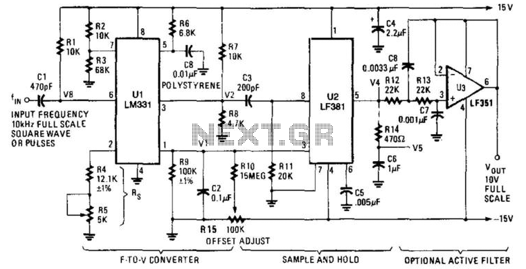
Description: U1 is a frequency-to-voltage converter that feeds a sample-and-hold circuit utilizing an LF381 operational amplifier. An LF351 provides a 10-V maximum scale output. The circuit generates a 1-V output per kHz frequency.
The described circuit employs a frequency-to-voltage conversion technique, where the component U1 converts an input frequency signal into a corresponding output voltage. This is achieved using an LF381 operational amplifier, which is known for its high performance in precision applications. The sample-and-hold circuit plays a critical role in capturing the output voltage level at specific intervals, ensuring accurate representation of the frequency signal over time.
The LF351 operational amplifier is integrated into the design to provide a stable and precise 10-V maximum scale output. This allows the circuit to handle a wide range of input frequencies while maintaining linearity and minimizing distortion. The output characteristic of 1-V per kHz indicates that for every kilohertz increase in the input frequency, the output voltage will increase by 1 volt. This linear relationship simplifies the interpretation of the output voltage in relation to the input frequency, making it suitable for applications requiring frequency measurement and conversion.
Overall, the combination of the LF381 and LF351 in this circuit design ensures high accuracy and reliability, making it effective for various electronic applications where frequency-to-voltage conversion is necessary. U1 is a frequency/voltage converter, feeding sample-and-hold circuit using an LF381. An LF 351 provides 10-V M-scale output. The circuit produces 1-V/kHz output.
The described circuit employs a frequency-to-voltage conversion technique, where the component U1 converts an input frequency signal into a corresponding output voltage. This is achieved using an LF381 operational amplifier, which is known for its high performance in precision applications. The sample-and-hold circuit plays a critical role in capturing the output voltage level at specific intervals, ensuring accurate representation of the frequency signal over time.
The LF351 operational amplifier is integrated into the design to provide a stable and precise 10-V maximum scale output. This allows the circuit to handle a wide range of input frequencies while maintaining linearity and minimizing distortion. The output characteristic of 1-V per kHz indicates that for every kilohertz increase in the input frequency, the output voltage will increase by 1 volt. This linear relationship simplifies the interpretation of the output voltage in relation to the input frequency, making it suitable for applications requiring frequency measurement and conversion.
Overall, the combination of the LF381 and LF351 in this circuit design ensures high accuracy and reliability, making it effective for various electronic applications where frequency-to-voltage conversion is necessary. U1 is a frequency/voltage converter, feeding sample-and-hold circuit using an LF381. An LF 351 provides 10-V M-scale output. The circuit produces 1-V/kHz output.

High speed sample and hold
This circuit demonstrates a 10 V acquisition time of 900 ns with 0% accuracy and a droop rate of only 100 µV/ms at an ambient temperature of 25°C. A faster acquisition time can be achieved by using a smaller hold-capacitor...

Analog circuit enforces slow servo response
The all-analog circuit presented controls the rate at which a miniature turbojet engine can be throttled. Increasing or decreasing the throttle too quickly on a miniature turbojet engine, or any jet engine, can lead to quick failure in flight, causing...

EIGHT CHANNEL COMPUTERIZED 3SUP1 SUP SUB2 SUB DIGIT_VM
Displays up to eight different DC voltages on a CRT terminal of a microprocessor under keyboard control, using BASIC commands and a BASIC routine provided in the article. Utilizes a modified Motorola MC14433 dual-lamp integrating analog-to-digital converter. An unknown voltage...

Peak voltage sample and hold circuit
The peak voltage sample and hold circuit is illustrated in Figure 12-50. This circuit comprises the LF398 sample and hold chip and the LM311 voltage comparator. The LF398 is responsible for outputting and inputting voltages. The LM311 compares the input...

Sample and hold
The JFETs, Q1 and Q2, provide complete buffering to C1, the sample and hold capacitor. During the sample phase, Q1 is activated, establishing a low-resistance path (rds(on)) for charging C1. In the hold phase, Q1 is deactivated, leaving Q1 Id...

grid frequency
Wall sockets provide power in the form of a 230-volt sine wave, operating at a frequency of 50 hertz. This means that the voltage alternates between positive and negative at a rate of 50 full cycles per second. Different countries...
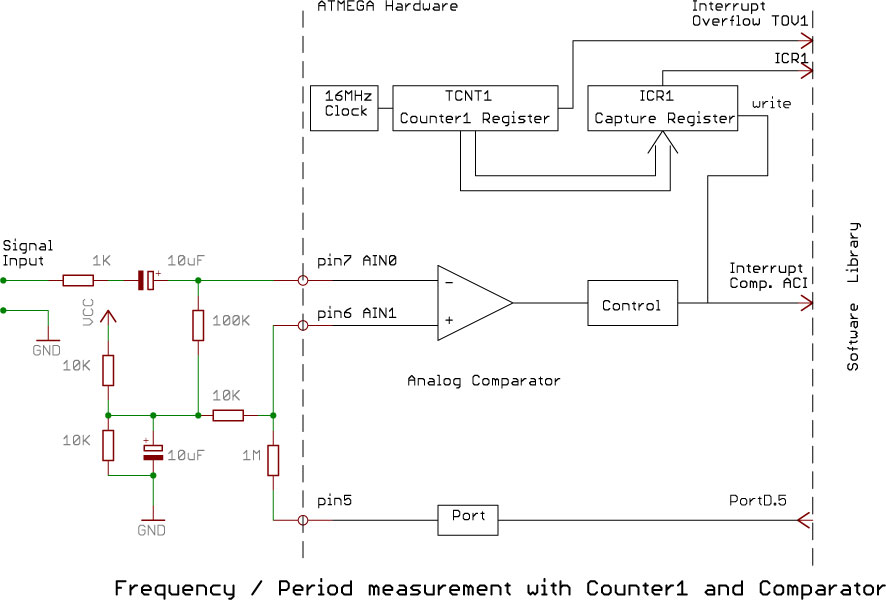
The Digital Sketchbook Arduino Frequency Measurement Library
Software on a MacBook Pro includes Laidman & Katsura's WaveWindow, which functions as a software oscilloscope. It is beneficial for individuals working with sound on the Mac, offering an educational and entertaining experience. Additionally, Faberacoustical's Signal Scope allows for the...

MFOS Micro-Sample & Hold circuit
The voltage to be sampled is applied to the input of R2, a 100K linear taper potentiometer, while the other end of R2 is grounded. Consequently, the signal level that is sent to the buffering level shifter U1-A and its...

Performance sample and hold
When switch SW1 is in the positive position, the FET is activated, exhibiting a resistance of approximately 400 ohms. The input voltage charges the capacitor through the FET. Conversely, when SW1 is in the negative position, the FET is deactivated...