


Illumination Intensity Measurement System Diagram

Description: This is an illumination intensity measurement system diagram. The data in the microprocessor is always in digital form. This is an illumination intensity measurement system diagram - Part 1. The data in the microprocessor is always in digital form.
The illumination intensity measurement system is designed to accurately capture and process light intensity levels using a microprocessor-based approach. The system typically consists of several key components, including a light sensor, signal conditioning circuitry, an analog-to-digital converter (ADC), and a microprocessor for data processing and analysis.
The light sensor, which may be a photodiode or a phototransistor, converts the incoming light into an electrical signal. This analog signal is often weak and requires amplification. The signal conditioning circuitry is responsible for filtering and amplifying the signal to ensure it is within the optimal range for the ADC. This stage may include operational amplifiers and passive components to refine the signal quality.
Once the signal is conditioned, it is fed into the ADC, which converts the analog voltage levels into a digital format that can be processed by the microprocessor. The ADC's resolution and sampling rate are critical parameters that determine the accuracy and responsiveness of the illumination intensity measurement.
The microprocessor receives the digital data from the ADC and performs various calculations and analyses. It can display the illumination intensity on an output device, such as an LCD screen, or transmit the data to a computer or other devices for further processing. The microprocessor may also include firmware that allows for calibration, data logging, and communication with other systems.
Overall, the illumination intensity measurement system is an essential tool for applications that require precise light level monitoring, such as in environmental studies, photography, and architectural lighting design. The system's ability to provide real-time digital data enhances its utility in various fields where light intensity plays a crucial role.This is Illumination Intensity Measurement System Diagram. The data in the microprocessor is always in digital form. This is Illumination Intensity Measurement System Diagram - Part 1. The data in the microprocessor is always in digital form..
The illumination intensity measurement system is designed to accurately capture and process light intensity levels using a microprocessor-based approach. The system typically consists of several key components, including a light sensor, signal conditioning circuitry, an analog-to-digital converter (ADC), and a microprocessor for data processing and analysis.
The light sensor, which may be a photodiode or a phototransistor, converts the incoming light into an electrical signal. This analog signal is often weak and requires amplification. The signal conditioning circuitry is responsible for filtering and amplifying the signal to ensure it is within the optimal range for the ADC. This stage may include operational amplifiers and passive components to refine the signal quality.
Once the signal is conditioned, it is fed into the ADC, which converts the analog voltage levels into a digital format that can be processed by the microprocessor. The ADC's resolution and sampling rate are critical parameters that determine the accuracy and responsiveness of the illumination intensity measurement.
The microprocessor receives the digital data from the ADC and performs various calculations and analyses. It can display the illumination intensity on an output device, such as an LCD screen, or transmit the data to a computer or other devices for further processing. The microprocessor may also include firmware that allows for calibration, data logging, and communication with other systems.
Overall, the illumination intensity measurement system is an essential tool for applications that require precise light level monitoring, such as in environmental studies, photography, and architectural lighting design. The system's ability to provide real-time digital data enhances its utility in various fields where light intensity plays a crucial role.This is Illumination Intensity Measurement System Diagram. The data in the microprocessor is always in digital form. This is Illumination Intensity Measurement System Diagram - Part 1. The data in the microprocessor is always in digital form..

light sensor circuit
This is a sensor circuit designed for light detection. It utilizes the LM311 comparator and features a simple design. The comparator is powered by a 12 V DC supply and does not require a negative supply for efficient operation. Feedback...

Light Pollution Meter
My circuit adds a transistor, to add feedback, and two resistors, to tailor the range of the control, with the result that a single-turn potentiometer gives a control range of about 2 to 30 microamps. I installed my circuit in...

shutter
A microprocessor-controlled shutter control box for electrically driven shutters, such as the MELLES GRIOT 04 IES 003 and ILEX electric shutters. Older view camera lenses often feature shutters that may develop issues due to age or wear. While a clean,...
light sensor
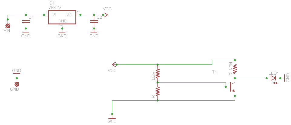
When connecting this element in a voltage divider configuration, a high and low signal can be generated based on the amount of light detected by the sensor. An NPN transistor configured as an inverter further filters this signal to produce...

home-made light-operated camera trigger
This device is designed to capture images of moving objects by activating a camera or flashgun when one or two light beams are interrupted. Originally intended for photographing insects in flight, it can also be utilized for projectiles and other...

Light Controlled Relays
The first circuit energizes the relay when the light rises above the preset level. The second circuit energizes the relay when the light falls below the preset level. The two circuits are practically identical. The only difference between them is...

LEGO Light SensorCircuit With LM358 IC
The following circuit illustrates a LEGO Light Sensor Circuit Diagram. This circuit is based on the LM358 integrated circuit, which features a dual operational amplifier and high-speed capabilities.
The LEGO Light Sensor Circuit utilizes the LM358, a versatile dual op-amp IC,...

Digital-data-line-receiver
When digital data is transmitted over long distances (greater than 1 meter), the integrity of the transfer can be compromised by parasitic effects such as ground level shifts and ground loops, in addition to extraneous noise that may be picked...
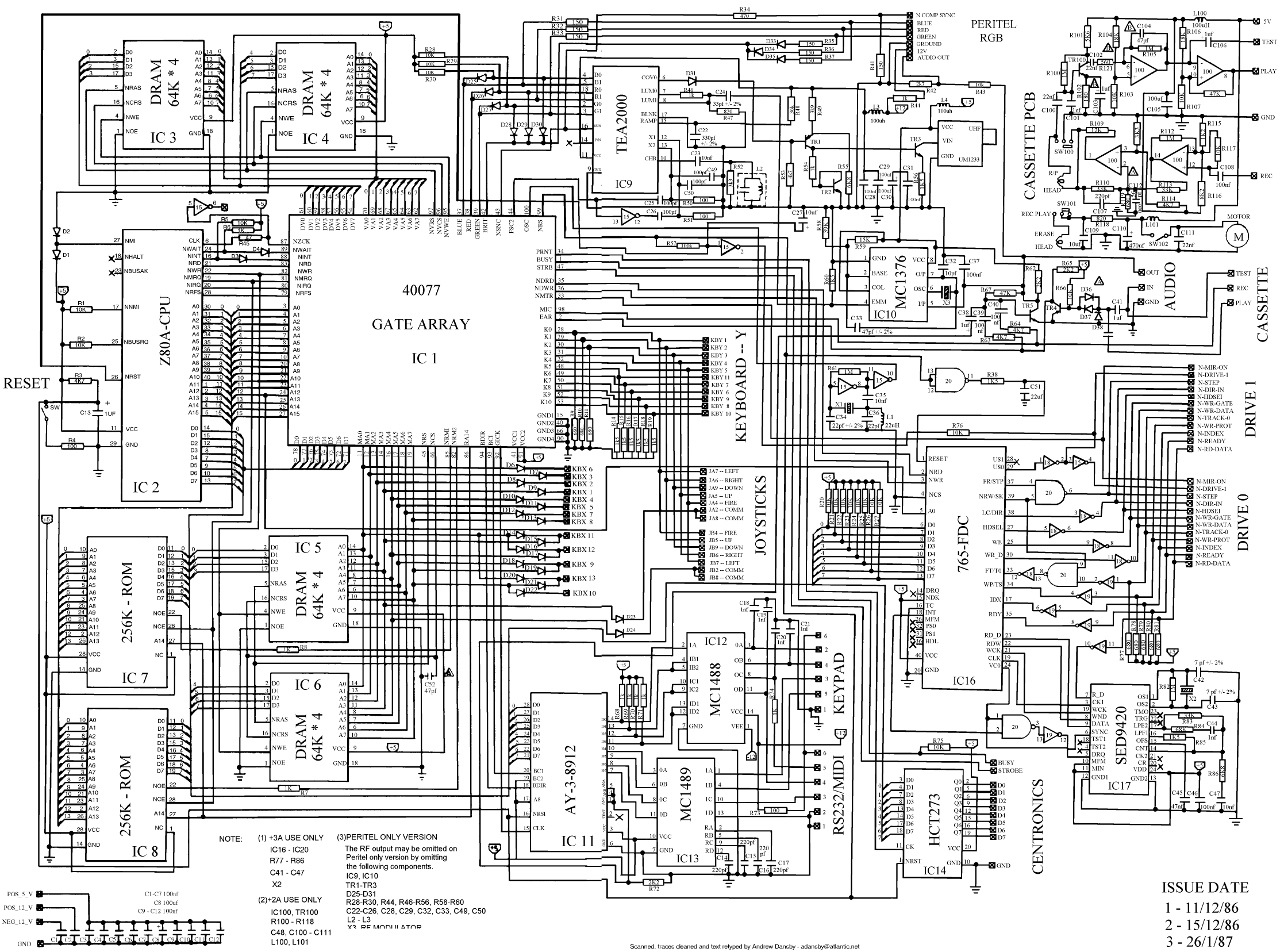
microprocessor Map processor to circuit diagram
How the processor produces 3 as the output. This question may be challenging to answer in simple terms. If so, a link to a book would be helpful.
The process by which a processor generates the output of the number 3...