


INA337 high-end configuration of the load current measurement shunt circuit diagram
#INA337
#current measurement
#shunt resistor
#voltage drop
#load current
#precision measurement
#analog circuit
#sensor interface

Description: The INA337 circuit, as illustrated, is part of a load current measuring shunt circuit. It generates a voltage drop across the sampling resistor Rs, which is connected in series between the power source and the load. The load current (IL) flows through Rs, and the resulting voltage drop indicates variations in the load current. This voltage drop across Rs serves as the input voltage to the INA337 amplifier output. It is crucial to select Rs such that the voltage drop does not exceed the maximum power supply rail voltage of 100 mV. The components R0 and C0 form an output filter network that effectively reduces noise from the circuit's output.
The INA337 is a precision instrumentation amplifier designed for low voltage applications, particularly in current sensing configurations. The shunt resistor Rs is a key component in this setup, and its value must be carefully chosen to ensure that the voltage drop remains within the specified limits while providing adequate sensitivity to changes in load current. Typically, Rs is selected based on the expected maximum load current and the desired voltage drop, ensuring that the voltage does not exceed the 100 mV threshold, which could lead to saturation of the amplifier and loss of accuracy.
The output filter network, consisting of resistor R0 and capacitor C0, plays a vital role in stabilizing the output signal from the INA337. This filter reduces high-frequency noise that may be present in the measurement due to external electromagnetic interference or inherent circuit noise, thus ensuring a cleaner signal for further processing or display. The design of R0 and C0 should be tailored to the specific application requirements, considering factors such as the desired cutoff frequency and the load characteristics.
In summary, the INA337 circuit configuration is essential for accurate load current measurement, relying on the precise selection of the shunt resistor and effective output filtering to maintain signal integrity. Proper implementation of this circuit allows for reliable monitoring of load conditions in various electronic applications, contributing to improved performance and efficiency. As shown in FIG INA337 constituted by the end of the load current measuring shunt circuit. Will produce a voltage drop when the circuit sampling resistor Rs in series between t he power source and the load, the load current IL flows through Rs, the voltage drop reflects the change in load current. The voltage drop on Rs as an input voltage, after INA337 amplifier output. Select the Rs should pay attention to the voltage drop on Rs formation can not exceed the power supply voltage Rail (Max) 100mV.
R0, C0, is the output filter network, you can filter out the noise output of the circuit.
The INA337 is a precision instrumentation amplifier designed for low voltage applications, particularly in current sensing configurations. The shunt resistor Rs is a key component in this setup, and its value must be carefully chosen to ensure that the voltage drop remains within the specified limits while providing adequate sensitivity to changes in load current. Typically, Rs is selected based on the expected maximum load current and the desired voltage drop, ensuring that the voltage does not exceed the 100 mV threshold, which could lead to saturation of the amplifier and loss of accuracy.
The output filter network, consisting of resistor R0 and capacitor C0, plays a vital role in stabilizing the output signal from the INA337. This filter reduces high-frequency noise that may be present in the measurement due to external electromagnetic interference or inherent circuit noise, thus ensuring a cleaner signal for further processing or display. The design of R0 and C0 should be tailored to the specific application requirements, considering factors such as the desired cutoff frequency and the load characteristics.
In summary, the INA337 circuit configuration is essential for accurate load current measurement, relying on the precise selection of the shunt resistor and effective output filtering to maintain signal integrity. Proper implementation of this circuit allows for reliable monitoring of load conditions in various electronic applications, contributing to improved performance and efficiency. As shown in FIG INA337 constituted by the end of the load current measuring shunt circuit. Will produce a voltage drop when the circuit sampling resistor Rs in series between t he power source and the load, the load current IL flows through Rs, the voltage drop reflects the change in load current. The voltage drop on Rs as an input voltage, after INA337 amplifier output. Select the Rs should pay attention to the voltage drop on Rs formation can not exceed the power supply voltage Rail (Max) 100mV.
R0, C0, is the output filter network, you can filter out the noise output of the circuit.

Line current measurement circuit
Detecting electrical equipment sometimes requires disconnecting the circuit in series for more accurate measurements of electrical current using an ammeter. However, restoring the circuit to its original state is necessary, as it can affect the normal operation of electrical equipment...

Summing CT Measurements
This could be achieved by monitoring separate points either through the same recorder or, less ideally, two separate recorders. In both cases, the results need to be artificially summed to obtain the total current draw. Two problems arise: first, the...

Current-shunt-amplifier
This circuit measures the power supply current of a circuit without using a current shunt resistor: R1 is only 3 cm of #20 gauge copper wire. A length of the power distribution wiring can be used for R1. The MAX420's...

A current - voltage conversion circuit
A current-voltage conversion circuit.
A current-voltage conversion circuit is designed to transform an input current signal into a corresponding voltage signal. This type of circuit is fundamental in various applications, including sensor interfacing, signal conditioning, and analog-to-digital conversion processes.
Typically, the...

high side current measurements
It is often challenging to measure the current in the positive lead of a power supply, such as a battery charger. Fortunately, specialized integrated circuits (ICs) have been developed for this purpose in recent years, including the Burr-Brown INA138 and...

Mathematical approch to measuring current voltage and resistance of mixed series and parallel
There is one significant low-impedance node in the entire circuit, referred to as 0V, located at the frame and the intersection in the middle. The upper voltage source is connected to this midpoint through a 1kΩ resistor, indicating that the...

voltage measurement Measure current on a constant current source
Measure current on a constant current source (LM317). Since a 3.3V chip is being used, a voltage divider is also required for reading the current. Will this circuit function correctly, or will it cause issues by attempting to increase voltage...

magnetics application schematics
Calibrate the measurement circuit by applying a known current to the conductor and measuring the resulting voltage output. If the displacement between the sensor and conductor changes, recalibration is necessary. This sensor circuit is capable of measuring both DC and...
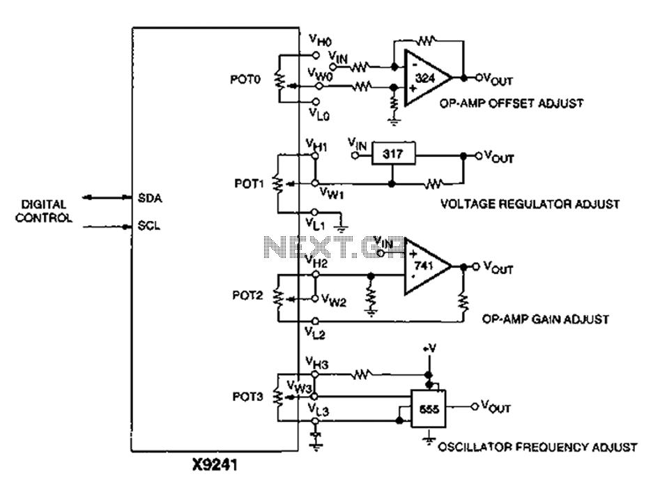
Corrector circuit diagram of an analog circuit
A XICOR X9241 POT IC module can be utilized to modify the four digital analog circuits, as depicted in the schematic.
The XICOR X9241 is a digital potentiometer integrated circuit designed for precise adjustment of analog signal levels in various electronic...