


LCD 7 digit HF counter

Description: The resistor between basis and collector (around 47k) is to be individually set according to transistor characteristics. Without PIC in socket at the collector should be 2.5 V.
The circuit described involves a transistor configuration where a resistor, typically valued at around 47k ohms, is placed between the base and collector terminals of a transistor. This resistor serves a critical role in determining the operating point of the transistor, allowing for adjustments based on the specific characteristics of the transistor used in the application.
In this configuration, the transistor operates in a common-emitter mode, where the base-emitter junction is forward-biased, and the collector-emitter junction is reverse-biased. The choice of resistor value is essential, as it influences the base current and, consequently, the collector current. A higher resistance value may result in reduced base current, which can lead to lower collector current, while a lower resistance value increases the base current, allowing for greater amplification.
The mention of a PIC (Peripheral Interface Controller) indicates that this circuit may be part of a larger system where the PIC controls the transistor's operation. In the absence of the PIC, it is specified that the voltage at the collector should be maintained at 2.5 V. This suggests that the circuit is designed to operate at a specific voltage level, which could be critical for interfacing with other components or for ensuring proper operation within the intended application.
The design allows for flexibility in tuning the circuit by changing the resistor value to match the characteristics of different transistors, which may have varying current gain (beta) values and threshold voltages. This adaptability is crucial in applications requiring precise control over signal amplification or switching functions. Overall, the configuration aims to achieve reliable performance while accommodating variations in transistor specifications.The resistor between basis and collector (around 47k) is to be individually set according transistor characteristics. Without PIC in socket at the collector should be 2.5 V.
The circuit described involves a transistor configuration where a resistor, typically valued at around 47k ohms, is placed between the base and collector terminals of a transistor. This resistor serves a critical role in determining the operating point of the transistor, allowing for adjustments based on the specific characteristics of the transistor used in the application.
In this configuration, the transistor operates in a common-emitter mode, where the base-emitter junction is forward-biased, and the collector-emitter junction is reverse-biased. The choice of resistor value is essential, as it influences the base current and, consequently, the collector current. A higher resistance value may result in reduced base current, which can lead to lower collector current, while a lower resistance value increases the base current, allowing for greater amplification.
The mention of a PIC (Peripheral Interface Controller) indicates that this circuit may be part of a larger system where the PIC controls the transistor's operation. In the absence of the PIC, it is specified that the voltage at the collector should be maintained at 2.5 V. This suggests that the circuit is designed to operate at a specific voltage level, which could be critical for interfacing with other components or for ensuring proper operation within the intended application.
The design allows for flexibility in tuning the circuit by changing the resistor value to match the characteristics of different transistors, which may have varying current gain (beta) values and threshold voltages. This adaptability is crucial in applications requiring precise control over signal amplification or switching functions. Overall, the configuration aims to achieve reliable performance while accommodating variations in transistor specifications.The resistor between basis and collector (around 47k) is to be individually set according transistor characteristics. Without PIC in socket at the collector should be 2.5 V.

Anti-saturation function delete circuit schematics
Anti-saturation devices have been removed from the UAA4002 routine applications. The base current of the switching transistor, which is driven by another transistor, is automatically adjusted. This adjustment allows the power transistors to operate in critical saturation. However, when the...

Ultra Low Power LCD
This circuit functions as an ultra-low power alternative to multiple LED on-off indicators. It is designed to be easily readable in full daylight conditions.
The described circuit employs a low-power microcontroller or a dedicated LED driver IC that manages the operation...

transistors How does this circuit diagram work
R2 controls the charging speed of capacitor C1. At a specific charge level, C1 triggers transistors Q1 and Q2, which release a 9-volt pulse. This pulse generates a clicking sound. The discharge process of the capacitor involves it charging gradually...

Free-Electron Pump (FEP) Experiments
A simple two-transistor inverter circuit has been constructed for this experiment. The transformer depicted is the inverter transformer. The output voltage from the inverter is in the form of pulses, with an estimated peak value of approximately 700V. When a...

Blinker circuit 2
The circuit depicted in Figure 13-4 utilizes triode control. Two transistors, VTi and VTz, are coupled via a capacitor (C) to alternately turn on and off, producing a flashing light effect. The flash frequency is influenced by the capacitance of...

Transistor Tutorial Power Amplifiers Part 4
An audio power amplifier can enhance weak signals from devices like tuners, CD players, or tape decks to fill a room with sound. This article emphasizes the operating principles and circuitry of low-frequency power amplifiers utilizing bipolar junction transistors (BJTs)....

2 transistor fm voice transmitter
This circuit functions as a voice transmitter utilizing a pair of BC548 transistors. While these transistors are not specifically designed for RF applications, they still yield satisfactory performance. An ECM microphone insert from Maplin Electronics, order code FS43W, is employed....
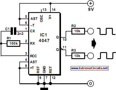
Liquid-Crystal Display (LCD) Tester
Liquid-crystal displays (LCDs) are available in various sizes and configurations, including their pinouts. Many of these displays require the manufacturer's documentation for proper usage, which is often difficult to locate when needed. Consequently, a small tester designed to identify the...

PIC Programmer
The uJDM PIC programmer circuit diagram is designed for programming simple microcontrollers such as the PIC16F84, PIC16F84A, and PIC16C84.
The uJDM PIC programmer is a compact and efficient circuit used for programming a range of Microchip PIC microcontrollers. It operates through...