


MAX12557 Schematic and Layout Suggestions
#high-speed data converters
#PC board layout
#bypassing
#decoupling
#schematic design
#layout guidelines
#signal integrity
#data acquisition
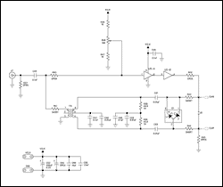
Description: This application note provides valuable PC board layout, bypassing, and decoupling guidelines for customers who are implementing high-speed data converters in their designs.
High-speed data converters are critical components in modern electronic systems, requiring careful consideration of their integration into printed circuit boards (PCBs). Effective PCB layout is essential to ensure optimal performance and reliability of these devices. The application note outlines several key guidelines that should be followed during the design phase.
Firstly, the layout of the PCB should minimize the length of the signal paths to reduce inductance and capacitance effects that can degrade signal integrity. This involves placing components such as data converters, amplifiers, and associated passive components in close proximity to each other. Additionally, using differential signaling can help mitigate noise and improve signal quality.
Bypassing and decoupling capacitors play a crucial role in maintaining stable power supply voltages and minimizing voltage fluctuations during high-speed operation. It is recommended to place these capacitors as close as possible to the power pins of the data converters. The use of low-ESR (Equivalent Series Resistance) capacitors is advised to ensure effective high-frequency performance.
Furthermore, ground planes should be employed to provide a low-impedance return path for signals, which helps to reduce electromagnetic interference (EMI) and enhances the overall performance of the circuit. Careful attention should also be paid to the routing of high-speed signals to avoid crosstalk and other forms of interference.
In summary, the application note serves as a comprehensive guide for engineers and designers working with high-speed data converters, emphasizing the importance of strategic PCB layout, effective bypassing, and decoupling techniques to optimize device performance. Following these guidelines will contribute to the reliability and efficiency of electronic systems utilizing high-speed data conversion technology.This application note provides valuable PC board layout, bypassing and decoupling guidelines for customers who are implementing high-speed data converters in their designs..
High-speed data converters are critical components in modern electronic systems, requiring careful consideration of their integration into printed circuit boards (PCBs). Effective PCB layout is essential to ensure optimal performance and reliability of these devices. The application note outlines several key guidelines that should be followed during the design phase.
Firstly, the layout of the PCB should minimize the length of the signal paths to reduce inductance and capacitance effects that can degrade signal integrity. This involves placing components such as data converters, amplifiers, and associated passive components in close proximity to each other. Additionally, using differential signaling can help mitigate noise and improve signal quality.
Bypassing and decoupling capacitors play a crucial role in maintaining stable power supply voltages and minimizing voltage fluctuations during high-speed operation. It is recommended to place these capacitors as close as possible to the power pins of the data converters. The use of low-ESR (Equivalent Series Resistance) capacitors is advised to ensure effective high-frequency performance.
Furthermore, ground planes should be employed to provide a low-impedance return path for signals, which helps to reduce electromagnetic interference (EMI) and enhances the overall performance of the circuit. Careful attention should also be paid to the routing of high-speed signals to avoid crosstalk and other forms of interference.
In summary, the application note serves as a comprehensive guide for engineers and designers working with high-speed data converters, emphasizing the importance of strategic PCB layout, effective bypassing, and decoupling techniques to optimize device performance. Following these guidelines will contribute to the reliability and efficiency of electronic systems utilizing high-speed data conversion technology.This application note provides valuable PC board layout, bypassing and decoupling guidelines for customers who are implementing high-speed data converters in their designs..
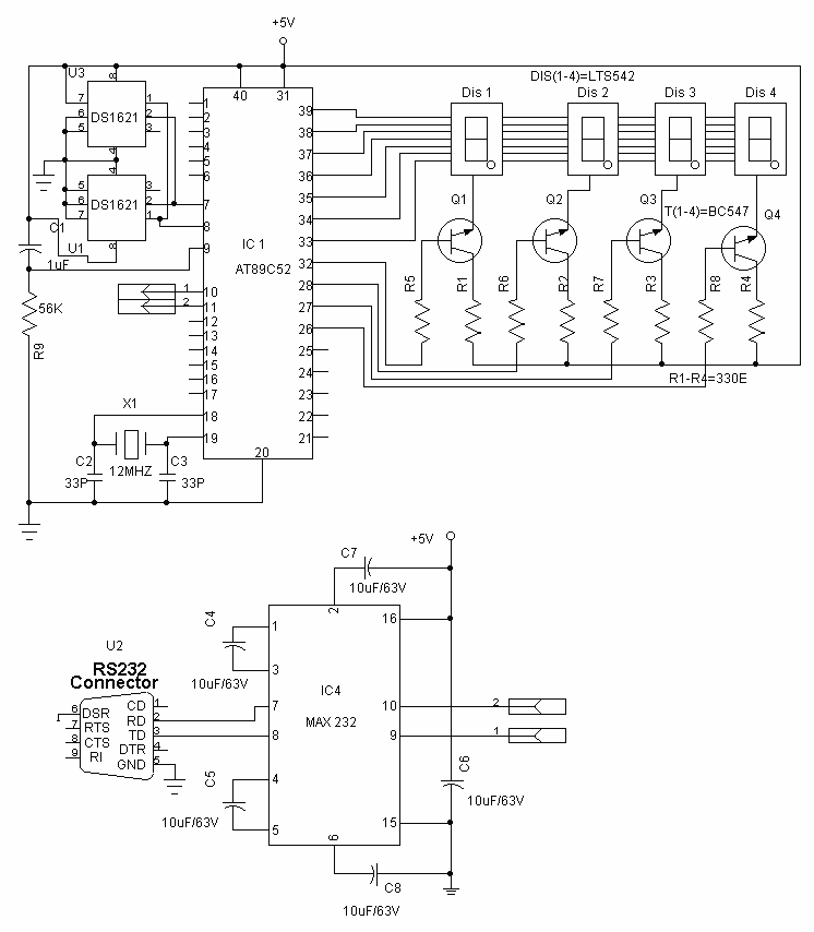
PC DATA LOGGER
Data acquisition is the process by which events in the real world are sampled and translated into machine-readable signals. Data acquisition typically involves sensors, transmitters and other instruments to collect signals, waveforms etc. to be processed and analyzed with a...
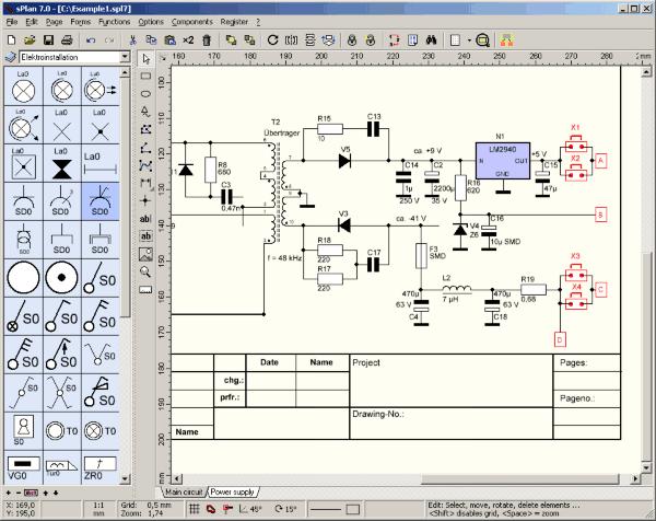
sPlan 6.0
sPlan is a software with already many thousands enthusiastic users. You need a software to design your schematic circuit diagrams easy and fast? You won't get past sPlan! No matter if you only want to sketch a little circuit diagram...

Data acquisition system circuit
Converters and data sampling: A 12-bit A/D converter, AD574, is interfaced with an 8031 microcontroller circuit. Parameters are measured by a multi-way switch after a CD4051 strobe signal is sent to the sample/hold input device. The selection of the input...

Proximity Camera Head (A2047) Manual
The Proximity Camera Head (A2047) is a Long-Wire Data Acquisition (LWDAQ) device that interfaces with a TC255P image sensor. It is a radiation-tolerant evolution of the Inplane Sensor Head (A2036). The A2036 and A2033 are frequently used with the LWDAQ...
wifilapper on a porsche 944 turbo t136
Following the successful development of a data acquisition box for a Porsche Chumpcar, which enabled the collection of lap times and telemetry data during an Auto Club Speedway race weekend, a new IOIO box is being designed specifically for a...

Data Acquisition System I
The HI-506 multiplexer functions as an analog input selector, which is controlled by a binary counter to select the appropriate channel. The HA-5330 serves as a high-speed sample and hold circuit. The sample/hold control is connected to the status (STS)...

Data acquisition system
Charge redistribution is utilized to achieve analog-to-digital (A/D) conversion. In standard applications, this operates as a ratiometric conversion system for a microprocessor, where V^p is connected to ground and VREF+ is connected to Vcc. The output will provide a straightforward...

CIRCUIT CREATOR- Schematic & PCB Design
Circuit CREATOR Electronics CAE System provides the most complete and high performance solution for electronics design using personal computers. More: Includes PCB DESIGN -layout editor and Schematic Capture software tool, full Schematic Design and Capture, Circuit Simulation, full interactive Symbol...

Fast data aquisition 2
A low-cost, high-speed monolithic analog multiplexer. The system operates by selecting a channel and initiating a conversion at a gain (G) of 1. It then examines the most significant bit (MSB) of the conversion result. If the MSB equals 1,...