


Peak-db-meter
#peak meter
#decibel meter
#exponential decay
#voltage comparator
#rectified input
#measurement circuit
#audio level
#capacitor
#resistor

Description: This circuit compares a rectified input voltage with a voltage that decays exponentially across a 4.7 kΩ resistor and a 0.01 µF capacitor. The comparison of the exponentially decaying voltage with the rectified input provides a peak-level indication that requires no adjustment. A phase-locked loop controls the scan rate so that each LED represents 6 dB within a 30 dB range.
The described circuit functions as a peak-level indicator using a rectified input voltage. The rectified voltage is compared against a reference voltage that is derived from an RC (resistor-capacitor) network, specifically a 4.7 kΩ resistor in series with a 0.01 µF capacitor. This RC combination creates an exponential decay response, allowing the circuit to measure transient signals effectively.
The operation begins with the rectification of an AC signal, which produces a pulsating DC voltage. This voltage is then fed into a comparator circuit that assesses its level against the exponentially decaying voltage produced by the RC network. As the input voltage rises, it will exceed the decaying voltage, triggering an output response that indicates the peak level of the input signal.
The phase-locked loop (PLL) integrated into the circuit plays a crucial role in controlling the scan rate of the output indicators, typically represented by LEDs. The PLL ensures that the scan rate is stable and synchronized with the input signal, allowing each LED to light up in increments that correspond to a 6 dB change in signal level. Given a total dynamic range of 30 dB, this results in five distinct LED indicators, providing a clear visual representation of the input signal's amplitude.
Overall, this circuit design is advantageous for audio applications, where monitoring signal levels is critical. The use of an RC network for voltage decay combined with the PLL for accurate timing ensures that the peak-level indication is both responsive and reliable, without necessitating manual adjustments.This circuit compares a rectified input, f."!N, with a voltage that decays exponentially across a 4. 7-KO resistor and a ·o.Ol-I"F capacitor. Comparing the exponentially decaying voltage with the rectified input provides a peak-level indication that requires no adjustment. A phase-locked loop controls the scan rate so that each LED represents 6 dB in the 30 dB range.
The described circuit functions as a peak-level indicator using a rectified input voltage. The rectified voltage is compared against a reference voltage that is derived from an RC (resistor-capacitor) network, specifically a 4.7 kΩ resistor in series with a 0.01 µF capacitor. This RC combination creates an exponential decay response, allowing the circuit to measure transient signals effectively.
The operation begins with the rectification of an AC signal, which produces a pulsating DC voltage. This voltage is then fed into a comparator circuit that assesses its level against the exponentially decaying voltage produced by the RC network. As the input voltage rises, it will exceed the decaying voltage, triggering an output response that indicates the peak level of the input signal.
The phase-locked loop (PLL) integrated into the circuit plays a crucial role in controlling the scan rate of the output indicators, typically represented by LEDs. The PLL ensures that the scan rate is stable and synchronized with the input signal, allowing each LED to light up in increments that correspond to a 6 dB change in signal level. Given a total dynamic range of 30 dB, this results in five distinct LED indicators, providing a clear visual representation of the input signal's amplitude.
Overall, this circuit design is advantageous for audio applications, where monitoring signal levels is critical. The use of an RC network for voltage decay combined with the PLL for accurate timing ensures that the peak-level indication is both responsive and reliable, without necessitating manual adjustments.This circuit compares a rectified input, f."!N, with a voltage that decays exponentially across a 4. 7-KO resistor and a ·o.Ol-I"F capacitor. Comparing the exponentially decaying voltage with the rectified input provides a peak-level indication that requires no adjustment. A phase-locked loop controls the scan rate so that each LED represents 6 dB in the 30 dB range.
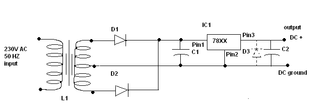
Power supply circuit design
C1 is a 1000 microfarad aluminum electrolytic capacitor. For loads less than 100mA, a 220 microfarad capacitor can be substituted. The voltage rating should be 2.5 times the output voltage.
C1 serves as a critical component in various electronic circuits, particularly...

Charging a low-voltage high-C capacitor. Efficiently
The first option is a Zener diode. There are several 2.2V Zener diodes available that could adequately protect the capacitor. However, a significant drawback is that half the energy may be wasted across the diode short. The question arises whether...

Car Large capacitor charge controllers
One-farad capacitors require some care. It's common knowledge that they must be pre-charged with a current-limiting resistor before plugging in. It is less common knowledge that those fifty-dollar smart cap controllers are in fact very simple devices, two dollars for...

adj pwr
The design incorporates a universal capacitor mounting and spacing feature, enabling compatibility with various capacitor types. It includes a mounting pattern suitable for TO-200 or TO-218/247 packages, specifically for the pass transistor and the transistor utilized in the current limit...

Voltage Comparator Circuits
This page provides basic information about voltage comparator integrated circuits and is to act as reference material for other circuits. The circuits shown are based on the LM339 Quad Voltage Comparator chip or the LM393 Dual Voltage Comparator chip. These...

How the capacitor works (in a debouncing circuit)
Understand why the LED does not light up, as the capacitor appears to be bypassing the switch. When the capacitor is fully charged, it does not conduct electricity. Although the individual is a beginner, after 20 hours of studying various...

Charged Capacitor to Light an LED
This project involves charging a capacitor with voltage, which will subsequently serve as a temporary power source for the circuit. After charging the capacitor with a battery, the battery is disconnected from the circuit. The capacitor then provides current to...
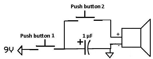
Apply a Pulse to a Speaker Using a Capacitor
This project demonstrates how a capacitor can supply a pulse signal to a speaker. A capacitor is charged and then discharges its voltage to a speaker, which acts as a transducer that converts electrical signals into sound. The result is...

Starting Capacitors
Instructions for electric motor start-run capacitors include the use of starting capacitors for air conditioner compressor motors and other electric motors like pumps. This involves diagnostic checks for start or run capacitors, including how to use a volt-ohm meter (VOM)...