


Rc Decade Box Circuit
#decade box
#resistance
#capacitance
#RC configurations
#low-pass filter
#high-pass filter
#precision components
#measurement tool
#circuit testing

Description: This decade box can be configured for any resistance value between 10 and 11.1 in 10-stop increments. A switch is employed to set various RC configurations. It is recommended to utilize precision components in the circuit. If feasible, verify components using an accurate bridge or other methods to ensure precision. The different configurations are determined using S13: (a) resistor only, (b) capacitor only (both in the r/c position); (c) series RC (in the ser position); (d) parallel RC (in the par position); (e) Low-Pass filter (in the lpf position); and (f) High-Pass Filter (in the hpf position). The terminal numbers indicated correspond to binding posts BP1-BP6.
This decade box circuit serves as a versatile tool for experimenting with various resistance values and RC configurations. The design allows for a range of resistance settings, enabling users to select increments of 10 ohms, providing flexibility for testing and calibration purposes. The inclusion of a switch for configuration selection enhances usability, allowing for quick transitions between different circuit setups.
Precision is crucial in this circuit; therefore, high-tolerance components are essential to maintain the integrity of the resistance values and the performance of the RC configurations. An accurate bridge should be employed to validate the component values, ensuring that the decade box operates within the desired specifications.
The configurations available through switch S13 allow for multiple applications. The resistor-only configuration is ideal for applications requiring a fixed resistance, while the capacitor-only configuration allows for capacitance testing. The series RC configuration is useful for analyzing the behavior of resistors and capacitors in series, while the parallel RC configuration is beneficial for studying parallel combinations. The low-pass filter configuration can be utilized to allow signals below a certain frequency to pass while attenuating higher frequencies, making it suitable for audio applications and signal processing. Conversely, the high-pass filter configuration permits signals above a certain frequency to pass, effectively blocking lower frequencies.
The terminal numbers BP1 to BP6 facilitate easy connections for external components, ensuring that users can quickly set up their experiments or applications. Each binding post corresponds to specific points in the circuit, enabling straightforward access to the various configurations and enhancing the overall functionality of the decade box. This decade box can be set for any resistance value between 10 and 11.1 in 10- stops. A switch can be used to configure several RC configurations. Use close tolerance components in the circuit. If possible, check components with-an accurate bridge or other means to ensure accuracy. THE VARIOUS CONFIGURATIONS are set using S13: (a) resistor only and (b) capacitor only (both in position r/c); (c) series RC (position ser); (cy parallel RC (position par); (e) Low-Pass filter (position lpf); and (f) High-Pass Filter (position hpf). The terminal numbers listed are those of bindinq-posts BP1-BP6.
This decade box circuit serves as a versatile tool for experimenting with various resistance values and RC configurations. The design allows for a range of resistance settings, enabling users to select increments of 10 ohms, providing flexibility for testing and calibration purposes. The inclusion of a switch for configuration selection enhances usability, allowing for quick transitions between different circuit setups.
Precision is crucial in this circuit; therefore, high-tolerance components are essential to maintain the integrity of the resistance values and the performance of the RC configurations. An accurate bridge should be employed to validate the component values, ensuring that the decade box operates within the desired specifications.
The configurations available through switch S13 allow for multiple applications. The resistor-only configuration is ideal for applications requiring a fixed resistance, while the capacitor-only configuration allows for capacitance testing. The series RC configuration is useful for analyzing the behavior of resistors and capacitors in series, while the parallel RC configuration is beneficial for studying parallel combinations. The low-pass filter configuration can be utilized to allow signals below a certain frequency to pass while attenuating higher frequencies, making it suitable for audio applications and signal processing. Conversely, the high-pass filter configuration permits signals above a certain frequency to pass, effectively blocking lower frequencies.
The terminal numbers BP1 to BP6 facilitate easy connections for external components, ensuring that users can quickly set up their experiments or applications. Each binding post corresponds to specific points in the circuit, enabling straightforward access to the various configurations and enhancing the overall functionality of the decade box. This decade box can be set for any resistance value between 10 and 11.1 in 10- stops. A switch can be used to configure several RC configurations. Use close tolerance components in the circuit. If possible, check components with-an accurate bridge or other means to ensure accuracy. THE VARIOUS CONFIGURATIONS are set using S13: (a) resistor only and (b) capacitor only (both in position r/c); (c) series RC (position ser); (cy parallel RC (position par); (e) Low-Pass filter (position lpf); and (f) High-Pass Filter (position hpf). The terminal numbers listed are those of bindinq-posts BP1-BP6.

A typical two high-pass filter circuit
A typical two high-pass filter circuit.
A high-pass filter (HPF) is an electronic circuit that allows signals with a frequency higher than a certain cutoff frequency to pass through while attenuating signals with frequencies lower than the cutoff frequency. A typical...
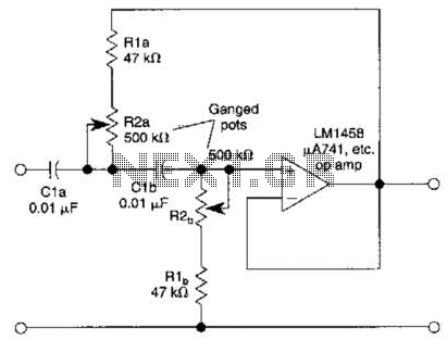
Variable High-Pass Filter Circuit
This second-order filter, designed for audio applications, utilizes an LM1458 or a similar operational amplifier. It is tunable with a cutoff frequency ranging from 30 Hz to 300 Hz. The resistors R2a and R2b are ganged log-taper potentiometers.
The described circuit...
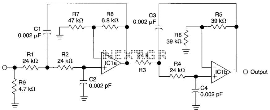
Active Fourth-Order Low-Pass Filter Circuit
This circuit is a fourth-order low-pass filter designed for operation at kilohertz frequencies. The component values for resistors R1, R2, and capacitors C1, C2, as well as resistors R3, R4 and capacitors C3, C4 can be adjusted for functionality at...

Capacitance meter
This project is exactly what you need. It is simple to construct and can be connected to almost any analogue multimeter. The scales are accurate over each range - certainly good enough to provide you with the value of any...

Cutoff frequency 48dB-octSCF low-pass filter circuit
To create a Butterworth low-pass filter with a 12 dB/octave roll-off, four second-order (12 dB/oct) filter blocks are connected in series. This configuration is intended to achieve flat response characteristics across the frequency spectrum. The values for each stage of...

Using the same parameters more convenient level 36dB-oct low-pass filter design
A 36 dB/octave Butterworth filter consists of three sub-structures, each stage containing two filter sections. The design aims to achieve specific 3 dB frequency characteristics. The filter needs to be normalized to a value of 0 across all levels, which...

A capacitance measuring circuit
A capacitive measuring instrument is a direct reading device that measures the capacitance of a circuit. This instrument is capable of measuring capacitance values ranging from a few picofarads to 0.1 microfarads, with specific ranges of 25 pF, 100 pF,...
Using the same parameters more convenient level 36dB-oct low-pass filter design
A 36 dB/octave Butterworth filter consists of three sub-structures, each stage containing two filter sections. The design aims to achieve specific 3 dB frequency characteristics. The filter needs to be normalized to a value of 0 across all levels, which...

Capacitance-meter
U1a serves as an oscillator, while U1b functions as the measurement component of the circuit. It converts an unknown capacitance into a pulse-width modulated signal, similar to the operation of an automotive dwell meter. The meter is linear, meaning that...