


Simple Circuit to Turn your Oscilloscope into a TDR
#oscilloscope
#TDR
#time domain reflectometer
#pulse
#cable
#measurement
#instrumentation
#electronics

Description: This simple circuit allows the use of an oscilloscope as a Time Domain Reflectometer (TDR). The operation involves sending a pulse down a cable and observing the resulting reflections.
The circuit design for utilizing an oscilloscope as a Time Domain Reflectometer (TDR) involves several key components and configurations to accurately measure and visualize signal reflections in transmission lines. The primary function of a TDR is to assess the integrity of a cable by sending a fast electrical pulse and analyzing the reflections caused by impedance mismatches along the cable.
To construct this circuit, a pulse generator is required to create the initial signal pulse. This pulse is typically a fast rise-time square wave, which can be generated using a 555 timer IC or a dedicated pulse generator module. The output of the pulse generator is connected to the input of the transmission line or cable under test.
The cable should be terminated at the far end with a known impedance to facilitate accurate measurement of reflections. Commonly, a 50-ohm or 75-ohm termination is used, depending on the specific application and the characteristics of the cable. If the termination is not matched to the cable impedance, reflections will occur, which can be analyzed by the oscilloscope.
The oscilloscope is connected to the same point as the pulse generator, typically through a suitable probe or attenuator to prevent loading effects that could distort the measurements. The oscilloscope is set to trigger on the leading edge of the pulse, allowing it to capture and display the waveform as it travels down the cable and reflects back.
The resulting waveform displayed on the oscilloscope will show the initial pulse followed by any reflections. The time delay between the original pulse and the reflected signals can be used to calculate the distance to the point of reflection, providing insights into the location of faults or discontinuities within the cable.
In summary, this circuit effectively transforms an oscilloscope into a TDR by utilizing a pulse generator, a transmission line, and an oscilloscope to analyze signal reflections, thereby enabling the detection of cable integrity issues. Proper calibration and setup are essential for obtaining accurate measurements and reliable results.This simple circuit allows you to use your oscilloscope as a Time Domain Reflectometer (TDR). This is how it works. Send a pulse down a cable and watch for the.
The circuit design for utilizing an oscilloscope as a Time Domain Reflectometer (TDR) involves several key components and configurations to accurately measure and visualize signal reflections in transmission lines. The primary function of a TDR is to assess the integrity of a cable by sending a fast electrical pulse and analyzing the reflections caused by impedance mismatches along the cable.
To construct this circuit, a pulse generator is required to create the initial signal pulse. This pulse is typically a fast rise-time square wave, which can be generated using a 555 timer IC or a dedicated pulse generator module. The output of the pulse generator is connected to the input of the transmission line or cable under test.
The cable should be terminated at the far end with a known impedance to facilitate accurate measurement of reflections. Commonly, a 50-ohm or 75-ohm termination is used, depending on the specific application and the characteristics of the cable. If the termination is not matched to the cable impedance, reflections will occur, which can be analyzed by the oscilloscope.
The oscilloscope is connected to the same point as the pulse generator, typically through a suitable probe or attenuator to prevent loading effects that could distort the measurements. The oscilloscope is set to trigger on the leading edge of the pulse, allowing it to capture and display the waveform as it travels down the cable and reflects back.
The resulting waveform displayed on the oscilloscope will show the initial pulse followed by any reflections. The time delay between the original pulse and the reflected signals can be used to calculate the distance to the point of reflection, providing insights into the location of faults or discontinuities within the cable.
In summary, this circuit effectively transforms an oscilloscope into a TDR by utilizing a pulse generator, a transmission line, and an oscilloscope to analyze signal reflections, thereby enabling the detection of cable integrity issues. Proper calibration and setup are essential for obtaining accurate measurements and reliable results.This simple circuit allows you to use your oscilloscope as a Time Domain Reflectometer (TDR). This is how it works. Send a pulse down a cable and watch for the.

Blanket internal measurement circuit disconnection
The internal disconnection circuit for a blanket operates on the principle of induction. It includes a wire approximately 2 cm in length that senses the proximity of a charged mains power source. When the sensing wire is close to the...

Digital-ProfiLab 4.0
Digital-ProfiLab was designed for measurement and control applications, combining features like circuit and logic simulation, front panel design, and hardware control to one powerful tool. Incoming signals from external devices may be processed and displayed. A circuit editor is used...

Oscilloscope-preamplifier
This circuit provides approximately 20 dB of voltage gain with a frequency range from 0.5 to 50 MHz. The low-frequency response of this circuit can be extended by increasing the value of the 0.05 µF capacitor or by removing the...

Digital Storage Oscilloscope Adapter
A follow up Mk2 version described by EA's Jim Rowe in the May/June/July 94 issues of EA improved on the original with calibrated time and vertical scales, and extra triggering features. This design proved even more popular than the first,...

Gated pulse descrambler
This circuit includes an amplifier and a video detector along with a secondary subcarrier detector for synchronization recovery. A pulse-former circuit modulates the gain of the main channel, enhancing it during synchronization intervals. Additionally, there is a provision for subcarrier...

Wireless Electronics for Communication
For all measurements with the oscilloscope, use the oscilloscope probe with a 10:1 attenuation to minimize measurement errors caused by the capacitance of coaxial cables and the input resistance of the oscilloscope. Problem 1 aims to simulate, build, and measure...

Dual-trace, triggered oscilloscope
This site contains public-domain schematics for a dual-trace, triggered oscilloscope, and some theory. Click on the topic in the table below to see the schematic for that block. I designed and built this oscilloscope in 1986 using the chassis of...
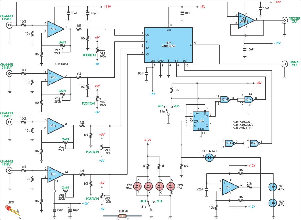
Four-Channel Oscilloscope Adaptor
This circuit allows the simultaneous display of four signals using a single channel of an oscilloscope. It effectively switches each of the inputs to the oscilloscope.
The circuit utilizes a multiplexer to manage the input signals. A typical configuration would involve...

Electronics Projects Circuits
Over 1400 top electronics projects and electronic circuits with photos, datasheets, and easy-to-read schematics, along with explanations of how they work and how to build them.
The collection comprises a vast array of electronics projects suitable for enthusiasts and professionals alike....