


SIMPLE HARMONIC DISTORTION ANALYZER
#THD
#op-amp
#notch filter
#tunable frequency
#CMOS
#voltage-followers
#Q factor
#harmonic distortion
#TLC272
#1000 Hz

Description: This Total Harmonic Distortion (THD) circuit differs from typical designs as it operates at a standard frequency of 1000 Hz while also being tunable between 970 Hz and 1030 Hz. It features an adjustable Q factor ranging from 0.3 to over 50. The operational amplifier used is a TLC272 CMOS unit, which includes two voltage followers necessary for buffering the input to the bootstrapped twin-T notch filter. Tuning is achieved through the use of three standard linear-taper slide pots, R1, R2, and R3, which are mounted side-by-side and have their sliders glued together for synchronized adjustment. Additionally, it is recommended to use twisted pair wiring for the circuit's input and output. To calibrate the circuit, a 1000-V RMS signal at 2000 Hz should be applied, with switch S1 set to TEST, and R7 adjusted until a reading of 0.99-V RMS is observed on a true-RMS voltmeter at the output. For circuit operation, switch S1 should be set to TUNE, a 1000 Hz sine-wave signal should be fed into the amplifier under test, and the amplifier's output connected to the THD adapter. The tuning pots R1, R2, and R3 should be adjusted to achieve the lowest output signal. After tuning, switch S1 should be set back to TEST to read the RMS voltage. The percentage of THD can then be calculated using the appropriate formula.
The THD circuit is designed to provide precise measurements of harmonic distortion in audio signals. The operational amplifier TLC272 is selected for its low noise characteristics and high slew rate, making it suitable for audio applications. The twin-T notch filter configuration is effective in attenuating specific frequencies, allowing for the measurement of distortion at the desired frequency range.
The tuning mechanism, utilizing linear-taper slide pots, allows for fine adjustments to both frequency and Q factor, facilitating accurate calibration and measurement. The Q factor, which represents the selectivity of the filter, can be adjusted to suit different testing conditions, providing flexibility in various applications.
For optimal performance, the use of twisted pair wiring minimizes electromagnetic interference, ensuring that the integrity of the input and output signals is maintained. Calibration is critical; thus, the initial setup with a 2000 Hz signal ensures that the circuit is accurately aligned before any measurements are taken.
When in operation, the circuit's ability to detect the lowest output signal during tuning is vital for determining the actual THD. The process of switching between TUNE and TEST modes allows for a straightforward workflow, enabling users to efficiently assess the performance of audio amplifiers or other signal-processing devices.
The final calculation of THD percentage is essential for quantifying the distortion present in the signal, providing valuable insights for audio engineers and technicians working to improve sound quality in various electronic devices.This THD circuit is somewhat different from the usual types: it can operate at the standard fre-quency of 1000 Hz, but it also is tunable from 970 Hz to 1030 Hz, and has an adjustable Q factor of 0. 3 to over 50. Op-amp UI, a TLC272 CMOS unit, contains the two voltage-followers required to buffer the input to the bootstrapped twin-T notch filter.
T uning is accomplished by R1, R2, and R3, which are standard linear-taper slide pots "ganged" together by mounting them side-by-side and glu-ing their sliders together. The only other intportant construction hint is to use twisted pair at the cir-cuit`s input and output.
To calibrate the circuit, input a 1000-V RMS signal at 2000 Hz, set 51 to TEST, and adjust R7 for a reading of 0. 99-V RMS on a true-RMS voltmeter at the output. To use the circuit, set 51 to TUNE, input a 1000-Hz sine-wave signal to the amplifier under test, and set the amplifier`s output to the THD adapter and tune R1/R2/R3 for the lowest output signal.
Then, set 51 to TEST and read the RMS voltage. To calculate the percent THD use:
The THD circuit is designed to provide precise measurements of harmonic distortion in audio signals. The operational amplifier TLC272 is selected for its low noise characteristics and high slew rate, making it suitable for audio applications. The twin-T notch filter configuration is effective in attenuating specific frequencies, allowing for the measurement of distortion at the desired frequency range.
The tuning mechanism, utilizing linear-taper slide pots, allows for fine adjustments to both frequency and Q factor, facilitating accurate calibration and measurement. The Q factor, which represents the selectivity of the filter, can be adjusted to suit different testing conditions, providing flexibility in various applications.
For optimal performance, the use of twisted pair wiring minimizes electromagnetic interference, ensuring that the integrity of the input and output signals is maintained. Calibration is critical; thus, the initial setup with a 2000 Hz signal ensures that the circuit is accurately aligned before any measurements are taken.
When in operation, the circuit's ability to detect the lowest output signal during tuning is vital for determining the actual THD. The process of switching between TUNE and TEST modes allows for a straightforward workflow, enabling users to efficiently assess the performance of audio amplifiers or other signal-processing devices.
The final calculation of THD percentage is essential for quantifying the distortion present in the signal, providing valuable insights for audio engineers and technicians working to improve sound quality in various electronic devices.This THD circuit is somewhat different from the usual types: it can operate at the standard fre-quency of 1000 Hz, but it also is tunable from 970 Hz to 1030 Hz, and has an adjustable Q factor of 0. 3 to over 50. Op-amp UI, a TLC272 CMOS unit, contains the two voltage-followers required to buffer the input to the bootstrapped twin-T notch filter.
T uning is accomplished by R1, R2, and R3, which are standard linear-taper slide pots "ganged" together by mounting them side-by-side and glu-ing their sliders together. The only other intportant construction hint is to use twisted pair at the cir-cuit`s input and output.
To calibrate the circuit, input a 1000-V RMS signal at 2000 Hz, set 51 to TEST, and adjust R7 for a reading of 0. 99-V RMS on a true-RMS voltmeter at the output. To use the circuit, set 51 to TUNE, input a 1000-Hz sine-wave signal to the amplifier under test, and set the amplifier`s output to the THD adapter and tune R1/R2/R3 for the lowest output signal.
Then, set 51 to TEST and read the RMS voltage. To calculate the percent THD use:
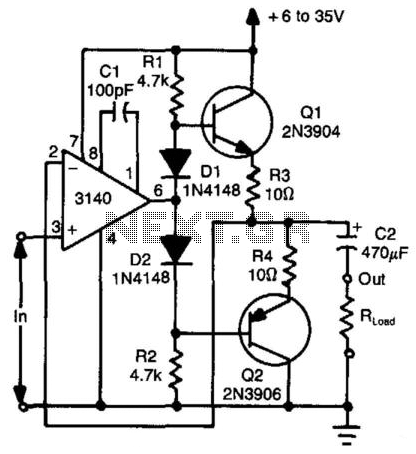
Bidirectional Compound Op Amp
Using two transistors (Q1 and Q2), a bidirectional operational amplifier can source or sink up to 50 mA. Diodes D1 and D2 provide biasing for Q1 to eliminate "dead-zone" effects.
The described circuit utilizes two transistors, Q1 and Q2, configured to...

simpler cmos single zone alarm
This circuit includes automatic exit and entry delays, a timed bell cut-off, and a system reset feature. It is designed to work with standard normally-closed input devices such as magnetic reed contacts, micro switches, foil tape, and passive infrared sensors...

Cmos-short-pulse-generator
The pulse generator consists of two low-power CMOS chips that produce a precise pulse width ranging from 50 to 500 ns. IC1 is a dual monostable multivibrator (one shot) where each positive trigger pulse initiates simultaneous positive output pulses at...

Op-Amp Microphone Preamp
A high-quality microphone preamplifier utilizing a single power supply, suitable for both dynamic and electret microphones. The operational amplifier (op-amp) employed can be any low-noise, high-performance type, such as the NE5534, TL071, or OPA 371. The schematic illustrates the configuration...

Flip-Flop Using CMOS NAND Gates
Using just two NAND or inverter gates, it is possible to build a D-type (or toggle) flip-flop with a push-button input. At power-up, the output of gate N2 is at a logical 1, ensuring that transistor T2 is switched off....

High-q-notch-filter
This circuit illustrates a twin-T network connected to an LM102 to form a high-Q, 60-Hz notch filter. The junction of R3 and C3, which is typically grounded, is bootstrapped to the output of the follower. Due to the low output...

LED sequencer
The model 4017 integrated circuit is a CMOS counter with ten output terminals. One of these ten terminals will be in a "high" state at any given time, with all others being "low," giving a "one-of-ten" output sequence. If low-to-high...

Oscillator Buffers
CMOS buffers added to an operational amplifier oscillator enhance performance, primarily due to the asymmetry and variability of the operational amplifier's output saturation voltages.
The integration of CMOS buffers into an operational amplifier (op amp) oscillator circuit serves to significantly improve...

Triangle Wave Generator
The second half of the circuit is an inverting integrator. The first operational amplifier (op-amp) begins with its two inputs in an unknown state; it can be assumed that it starts with the non-inverting input slightly higher than ground. The...