


Simple Portable Thermometer
#LM35DZ
#LM358
#microcontroller
#7-segment display
#temperature measurement
#portable
#battery-operated
#analogue to digital
#sensor
#BCD

Description: The device is user-friendly and consumes minimal current, allowing it to operate throughout the battery's shelf life. It employs a standard LM35DZ sensor (IC3) whose analog output voltage is buffered by an LM358 (IC2A). The voltage is processed by a microcontroller and converted into a BCD value for display on multiplexed 7-segment displays. The display automatically turns off after approximately 30 seconds unless button S1 is pressed, conserving battery power. Pressing the button again will show the current temperature. The prototype utilizes two 0.56-inch (14.2 mm) common cathode green displays to indicate the temperature, which ranges from 0 to 100 °C. Calibration against a known temperature is required upon initial use. The preset P1 can be adjusted to modify the temperature reading by approximately 4 °C. To calibrate, press the button and turn the preset until the correct temperature is displayed. The microcontroller employed is a PIC16F684, selected for its built-in functions and internal oscillator, which eliminates the need for an external crystal, thus freeing up I/O pins. The two 7-segment displays are multiplexed, with BC547 transistors used to alternately switch them on and off. Each display is blanked before showing a value to prevent ghosting. Temperature samples are read every 30 seconds to minimize fluctuations in the displayed value. An LP2950 is utilized to regulate the supply voltage to 5 V, functioning effectively down to 6 V to maximize battery usage. The thermometer can also operate on three AA dry batteries in series without a series regulator. The PIC software is available for free download from the Elektor website, archived under file number 080418-11.zip, and was developed using CCS C.
The circuit is designed to provide a compact, efficient temperature measurement solution with low power consumption, making it suitable for battery-operated applications. The LM35DZ temperature sensor offers a linear output voltage proportional to the temperature, which is buffered by the LM358 operational amplifier to ensure a stable signal for the microcontroller. The PIC16F684 microcontroller processes this signal, converting the analog voltage to a binary-coded decimal (BCD) format, which is then displayed on the multiplexed 7-segment displays.
The multiplexing technique employed allows for reduced power consumption as only one display is active at any given time. The use of BC547 transistors facilitates this switching, ensuring that each display is turned off before the next one is activated, effectively preventing ghosting effects during operation. The 30-second sampling interval for temperature readings is a strategic choice to balance responsiveness with power conservation.
The LP2950 voltage regulator ensures that the circuit operates within the required voltage range, even as the battery depletes. This low-dropout regulator is particularly advantageous in maximizing battery life, as it can maintain a stable output voltage until the battery voltage approaches the regulator's minimum input voltage threshold. The option to power the device with three AA batteries directly without a regulator adds to the versatility of the design, allowing for straightforward implementations in various environments.
Calibration is a critical aspect of ensuring measurement accuracy. The inclusion of a preset potentiometer (P1) allows users to fine-tune the temperature readings against a known reference, ensuring that the device remains accurate over time. Overall, this design combines functionality with ease of use, making it an excellent choice for portable temperature measurement applications.It is very easy to use and consumes so little current that it will work for the battery`s shelf life. The circuit uses a standard LM35DZ sensor (IC3) whose analogue output voltage is buffered by an LM358 (IC2A).
The voltage is read by the microcontroller and converted into a BCD value so it can appear on the multiplexed 7-segment displays. The display will switch off after approximately 30 s unless button S1 is pressed. In this way battery power is conserved. Pressing the button again will show the temperature. In the prototype two 0. 56 (14. 2 mm) common cathode (CC) green displays were used to show the current value of the temperature. The meter can show temperatures between 0 and 100 C. The first time it is used the meter has to be calibrated against a known reading. Preset P1 can be varied to change the value of the temperature by about 4 C. Press the but-ton and then turn the preset until the correct value of the temperature is shown. The microcontroller used is a PIC16F684. This has been chosen because it has a number of inbuilt functions and most importantly an internal oscillator which obviates the need for an external crystal, freeing up pins for I/O activities. Two 7-segment displays are connected in a multiplexed fashion. The displays are alternately switched on and off by the BC547 transistors. Each display is blanked before displaying the value to prevent ghosting. A temperature sample is read every 30 s to prevent the value displayed from changing due to fluctuations in the temperature.
An LP2950 is used to regulate the supply volt-age to 5 V. This is a low dropout regulator which can work down to 6 V hence juicing the battery for the last drop of energy. The thermometer may also be run from three AA dry batteries in series with no series regulator. The PIC software can be downloaded free of charge from the Elektor website. The archive file number is 080418-11. zip. The software was developed using CCS C.
The circuit is designed to provide a compact, efficient temperature measurement solution with low power consumption, making it suitable for battery-operated applications. The LM35DZ temperature sensor offers a linear output voltage proportional to the temperature, which is buffered by the LM358 operational amplifier to ensure a stable signal for the microcontroller. The PIC16F684 microcontroller processes this signal, converting the analog voltage to a binary-coded decimal (BCD) format, which is then displayed on the multiplexed 7-segment displays.
The multiplexing technique employed allows for reduced power consumption as only one display is active at any given time. The use of BC547 transistors facilitates this switching, ensuring that each display is turned off before the next one is activated, effectively preventing ghosting effects during operation. The 30-second sampling interval for temperature readings is a strategic choice to balance responsiveness with power conservation.
The LP2950 voltage regulator ensures that the circuit operates within the required voltage range, even as the battery depletes. This low-dropout regulator is particularly advantageous in maximizing battery life, as it can maintain a stable output voltage until the battery voltage approaches the regulator's minimum input voltage threshold. The option to power the device with three AA batteries directly without a regulator adds to the versatility of the design, allowing for straightforward implementations in various environments.
Calibration is a critical aspect of ensuring measurement accuracy. The inclusion of a preset potentiometer (P1) allows users to fine-tune the temperature readings against a known reference, ensuring that the device remains accurate over time. Overall, this design combines functionality with ease of use, making it an excellent choice for portable temperature measurement applications.It is very easy to use and consumes so little current that it will work for the battery`s shelf life. The circuit uses a standard LM35DZ sensor (IC3) whose analogue output voltage is buffered by an LM358 (IC2A).
The voltage is read by the microcontroller and converted into a BCD value so it can appear on the multiplexed 7-segment displays. The display will switch off after approximately 30 s unless button S1 is pressed. In this way battery power is conserved. Pressing the button again will show the temperature. In the prototype two 0. 56 (14. 2 mm) common cathode (CC) green displays were used to show the current value of the temperature. The meter can show temperatures between 0 and 100 C. The first time it is used the meter has to be calibrated against a known reading. Preset P1 can be varied to change the value of the temperature by about 4 C. Press the but-ton and then turn the preset until the correct value of the temperature is shown. The microcontroller used is a PIC16F684. This has been chosen because it has a number of inbuilt functions and most importantly an internal oscillator which obviates the need for an external crystal, freeing up pins for I/O activities. Two 7-segment displays are connected in a multiplexed fashion. The displays are alternately switched on and off by the BC547 transistors. Each display is blanked before displaying the value to prevent ghosting. A temperature sample is read every 30 s to prevent the value displayed from changing due to fluctuations in the temperature.
An LP2950 is used to regulate the supply volt-age to 5 V. This is a low dropout regulator which can work down to 6 V hence juicing the battery for the last drop of energy. The thermometer may also be run from three AA dry batteries in series with no series regulator. The PIC software can be downloaded free of charge from the Elektor website. The archive file number is 080418-11. zip. The software was developed using CCS C.

Automatic Switch Project
Model railroad turnouts, often referred to as switches, can be controlled in various ways. The simplest method is manual control, operated by hand. Remote activation is typically achieved through pneumatic (air) or electrical means. The project discussed in these articles...

Add a sensor to a board and measure something with it
This week's plan is to build a device that warns of the potential for a knockdown, which is the process by which an over-canvassed ship is laid over on her beam-ends. The risk of sinking is high during this event,...

Speed Control of DC Motor using Microcontroller by using PWM ECE Project
This report details an electronic project focused on the speed control of a DC motor using a microcontroller and PWM (Pulse Width Modulation). The system integrates a microcontroller with an LCD, keypad, and a DC motor driver. The microcontroller generates...

ADT70 platinum resistance temperature measurement circuit
The AD170 basic electrical parameters include a temperature coefficient of 25 ppm/°C and a temperature measurement accuracy of ±1°C, with a maximum temperature range of -200°C to +100°C. The power supply required is +5V or -5V, and the operating temperature...

bcd diagram
The definition of ecotherm insulation is crucial, particularly regarding its application in circuits. This includes the use of half adders in parallel adder configurations and the logic connection diagrams for parallel BCD (Binary-Coded Decimal) systems. A proper understanding of the...
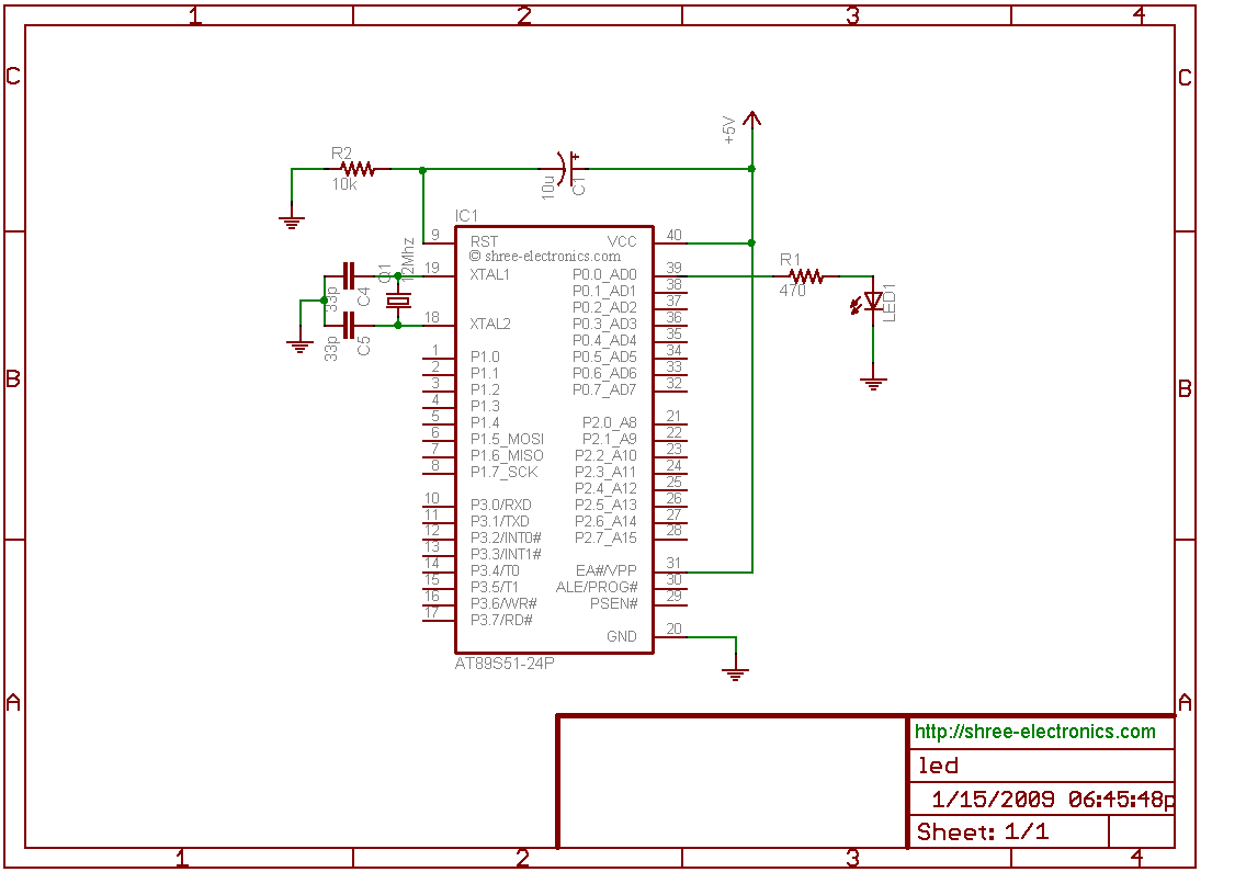
microcontroller led interfacing
The initial step often taken when learning about any microcontroller or embedded system is to make an LED blink. The circuit presented below illustrates the setup for interfacing an LED. Note: Due to the large dimensions of the circuit diagram,...

mosfet Turning a microcontroller on with a flip flop
The objective is to control the power to a load, specifically an 8051-based microcontroller (uC), using two switches. When the uC is powered on, it sets the PWR pin high. Upon pressing the switches again, pin 4 of the flip-flop...
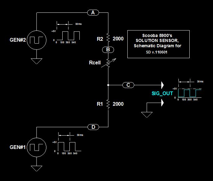
Scoobas Solution Sensing Tactic
This document serves multiple purposes, primarily to document the methods employed by a Scooba robot to detect: a) the presence of an acceptable cleaning solution being delivered to its pump, and b) the excess presence of used solution collected off...

Interface a uC to PC RS232 with MAX232A
This document outlines the standard configuration for interfacing a microcontroller, such as the 8051, with a PC using RS232 through the MAX232A. The UART or serial port was absent in the 8049 and 8749 microcontrollers, which were predecessors to the...