


Single chip checks resistance
#resistance tester
#LM324
#op amp
#current source
#voltage buffer
#voltage amplifier
#production line testing
#relay testing
#coil testing

Description: A simple tester can be utilized for routine resistance checks on production lines of relays, coils, or similar components where frequent resistance changes are not necessary. The tester is constructed around a single quad op-amp chip, the LM324. A resistor, chosen to be approximately 80 times the resistance being tested, is used alongside a 5 V supply to form the current source. The first op-amp buffers the voltage generated across the resistance under test, Rx. The second op-amp amplifies this voltage. The third and fourth op-amps compare the amplified voltage with predetermined high and low limits. These limits are set using multi-turn presets with high and low limit resistors connected in place of Rx. LED 1 (red) illuminates when the resistance is high. LED 2 (green) indicates that the resistance is within acceptable limits. LED 3 (red) signifies that the resistance is low.
The resistance tester circuit employs the LM324 quad op-amp, which consists of four independent, high-gain, frequency-compensated operational amplifiers. The circuit begins with a current source generated by a resistor connected to a 5 V supply. This resistor is strategically selected to be approximately 80 times the value of the resistance to be measured, ensuring that the circuit can effectively operate within its designed range.
The first op-amp functions as a buffer, isolating the test resistance Rx from the subsequent stages of the circuit. This buffering prevents loading effects that could alter the resistance measurement. The output from this op-amp is then fed into the second op-amp, which is configured as a non-inverting amplifier. This amplification stage is crucial for enhancing the voltage signal across Rx, making it easier to compare against the set limits.
The third and fourth op-amps are configured as comparators. They compare the amplified voltage against preset reference voltages that define the acceptable range for the resistance measurement. These reference voltages are established through multi-turn potentiometers, allowing for fine-tuning of the high and low limits. The use of potentiometers facilitates easy adjustment and calibration of the circuit to accommodate different resistance ranges.
The output of the comparators drives three LEDs, providing a visual indication of the resistance status. When the measured resistance exceeds the upper limit, LED 1 (red) lights up, signaling that the resistance is too high. Conversely, when the resistance falls below the lower limit, LED 3 (red) illuminates, indicating a low resistance condition. If the resistance is within the acceptable range, LED 2 (green) lights up, confirming that the measurement is within limits. This LED indication system allows for quick and easy assessment of the resistance status, making the tester a valuable tool for production line applications.A simple tester can be used for routine checks for resistance on production lines of relays, coils, or similar components where frequent changes in resistance to be tested are not required. The tester is built around a single quad op amp chip, the LM324. R, which is chosen to be around 80 times the resistance to be checked, and the 5 V supply form the current source.
The first op amp buffers the voltage generated across the resistance tinder test, Rx. The second op amp amplifies this voltage. The third and fourth op amps compare the amplified voltage with high and low limits. The high and low limits are set on multitum presets with high and low limit resistors connected in place of Rx. LED 1 (red) lights when the resistance is high. LED 2 (green) shows that the resistance is within limits. LED 3 (red) indicates that the resistance is low.
The resistance tester circuit employs the LM324 quad op-amp, which consists of four independent, high-gain, frequency-compensated operational amplifiers. The circuit begins with a current source generated by a resistor connected to a 5 V supply. This resistor is strategically selected to be approximately 80 times the value of the resistance to be measured, ensuring that the circuit can effectively operate within its designed range.
The first op-amp functions as a buffer, isolating the test resistance Rx from the subsequent stages of the circuit. This buffering prevents loading effects that could alter the resistance measurement. The output from this op-amp is then fed into the second op-amp, which is configured as a non-inverting amplifier. This amplification stage is crucial for enhancing the voltage signal across Rx, making it easier to compare against the set limits.
The third and fourth op-amps are configured as comparators. They compare the amplified voltage against preset reference voltages that define the acceptable range for the resistance measurement. These reference voltages are established through multi-turn potentiometers, allowing for fine-tuning of the high and low limits. The use of potentiometers facilitates easy adjustment and calibration of the circuit to accommodate different resistance ranges.
The output of the comparators drives three LEDs, providing a visual indication of the resistance status. When the measured resistance exceeds the upper limit, LED 1 (red) lights up, signaling that the resistance is too high. Conversely, when the resistance falls below the lower limit, LED 3 (red) illuminates, indicating a low resistance condition. If the resistance is within the acceptable range, LED 2 (green) lights up, confirming that the measurement is within limits. This LED indication system allows for quick and easy assessment of the resistance status, making the tester a valuable tool for production line applications.A simple tester can be used for routine checks for resistance on production lines of relays, coils, or similar components where frequent changes in resistance to be tested are not required. The tester is built around a single quad op amp chip, the LM324. R, which is chosen to be around 80 times the resistance to be checked, and the 5 V supply form the current source.
The first op amp buffers the voltage generated across the resistance tinder test, Rx. The second op amp amplifies this voltage. The third and fourth op amps compare the amplified voltage with high and low limits. The high and low limits are set on multitum presets with high and low limit resistors connected in place of Rx. LED 1 (red) lights when the resistance is high. LED 2 (green) shows that the resistance is within limits. LED 3 (red) indicates that the resistance is low.
amplifier tutorial
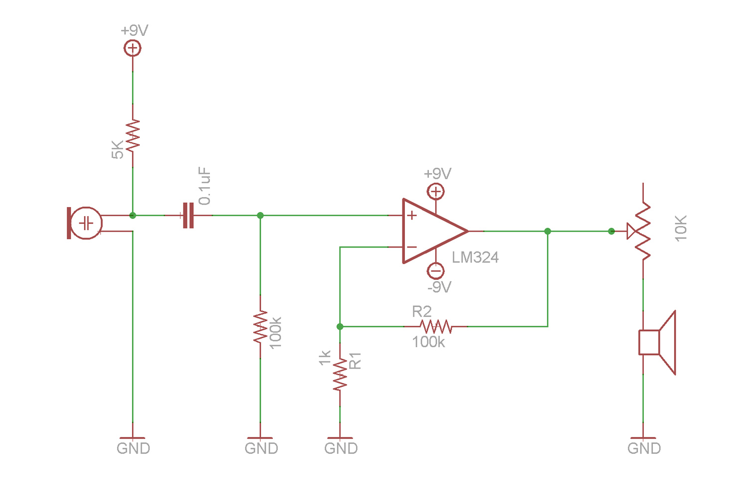
This video demonstrates the fundamentals of operational amplifiers (op amps) and includes an example circuit that amplifies a small microphone signal to make it audible through earbuds. The circuit utilizes the LM324 quad op amp integrated circuit (IC).
The described circuit...

Window Generator
This window generator utilizes a single LM324 operational amplifier and includes two adjustable set points. When the two comparators formed by U1B go high, LED1 illuminates. When U1C goes high, the LED turns off. Hysteresis is implemented using 10 MΩ...
fast voltage driven current source
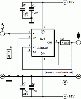
The current source in the diagram reacts very quickly to changes in the input signal and may be utilized in specific measurements. The differential amplifier IC1 ensures that the voltage across resistor R2 is equal to the input voltage, represented...
Nodal Analysis of Op Amp Circuits
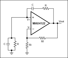
This application note explains how the transfer function of most operational amplifier circuits can be derived through a straightforward process of nodal analysis.
The transfer function of operational amplifier (op amp) circuits is a critical aspect for understanding their behavior in...

Voltage comparator circuit
An operational amplifier (op amp) is utilized as a comparator and as a current sink for an LED. The output voltage of the amplifier varies by approximately 1.4 V based on the direction of the current. At any given moment,...

Offset-Adjusting Current Source Circuit
This setup can function as a cost-effective current source with an output accuracy of 1%. However, the voltage offset can activate the current source even when Vqq equals Vin. Modifying the configuration of Figure 1 can resolve the issue of...

Current source
This precision current source features output current ranges from 10 µA to 10 mA, with an output compliance of 30 V to -5 V. The output current is fully adjustable within each range using a calibrated ten-turn potentiometer. An error...

Recording Level Meter Circuit
The circuit illustrates a two-stage voltage amplifier that drives a recording level meter. An AC signal input is amplified and rectified, with the resulting DC voltage displayed on the meter. This circuit is compatible with tape recorders or audio mixers...

Simple Parking Sensor Using LM324
The circuit diagram represents a simple parking sensor system that measures the distance between the rear bumper of a vehicle and obstacles located behind it. The schematic consists of two main components: the transmitter and the receiver. The distance measurement...