


Single-chip TRMS Power Measurement System AD8362 Demodulation
#AD8362
#demodulation
#RF
#power measurement
#envelope detection
#sine wave
#signal processing
#instrumentation
#circuit design
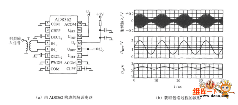
Description: The UTGT side of the AD8362 can be utilized to create a demodulation circuit. It extracts the envelope from the RF amplitude and converts it into a low and mid-frequency signal prior to demodulation. The waveforms associated with the demodulation circuit and the process of envelope extraction are illustrated in Figures (a) and (b) below. It is assumed that the input signal is a modulated 100 kHz sine wave.
The AD8362 is a versatile RF envelope detector and demodulator that operates effectively in various applications, including communication systems and signal processing. The primary function of the UTGT side is to perform envelope detection, which is critical for recovering the original information signal from a modulated carrier wave.
In the demodulation circuit, the input signal, which is a modulated 100 kHz sine wave, is fed into the AD8362. The device employs a combination of analog signal processing techniques to extract the envelope of the RF signal. This involves rectification and low-pass filtering, which allows the circuit to isolate the amplitude variations corresponding to the original modulation.
The output of the demodulation process is a low-frequency signal that mirrors the envelope of the input RF amplitude. This output can be further processed or analyzed in various applications, such as audio signal recovery or data transmission. The waveforms depicted in the provided figures illustrate the relationship between the input RF signal, the detected envelope, and the resulting low-frequency output, highlighting the effectiveness of the AD8362 in demodulation tasks.
Overall, the AD8362's ability to efficiently demodulate RF signals makes it a valuable component in modern electronic designs, particularly in systems where accurate signal recovery is essential. The integration of this functionality into a single chip simplifies the design process and enhances the reliability of the overall system.AD8362`s UTGT side can constitute demodulation circuit. Take the envelope from the RF amplitude and restore it to the low and middle frequency signal before demodulation. The waveforms of the applied demodulation circuit and the process of obtaining envelope are shown in Figure (a), (b) below.
It is assumed that the input signal is modulated 100kHz sine wave..
The AD8362 is a versatile RF envelope detector and demodulator that operates effectively in various applications, including communication systems and signal processing. The primary function of the UTGT side is to perform envelope detection, which is critical for recovering the original information signal from a modulated carrier wave.
In the demodulation circuit, the input signal, which is a modulated 100 kHz sine wave, is fed into the AD8362. The device employs a combination of analog signal processing techniques to extract the envelope of the RF signal. This involves rectification and low-pass filtering, which allows the circuit to isolate the amplitude variations corresponding to the original modulation.
The output of the demodulation process is a low-frequency signal that mirrors the envelope of the input RF amplitude. This output can be further processed or analyzed in various applications, such as audio signal recovery or data transmission. The waveforms depicted in the provided figures illustrate the relationship between the input RF signal, the detected envelope, and the resulting low-frequency output, highlighting the effectiveness of the AD8362 in demodulation tasks.
Overall, the AD8362's ability to efficiently demodulate RF signals makes it a valuable component in modern electronic designs, particularly in systems where accurate signal recovery is essential. The integration of this functionality into a single chip simplifies the design process and enhances the reliability of the overall system.AD8362`s UTGT side can constitute demodulation circuit. Take the envelope from the RF amplitude and restore it to the low and middle frequency signal before demodulation. The waveforms of the applied demodulation circuit and the process of obtaining envelope are shown in Figure (a), (b) below.
It is assumed that the input signal is modulated 100kHz sine wave..

Single injector-tracer
In the "Trace" mode, the non-linear operation of the amplifier will detect modulated RF signals, which will be filtered by the 0.001 µF capacitor and heard in the headphones. In the "Inject" mode, this circuit will provide a nominal square...

Simple Rf Test Oscillator Circuit
A simple oscillator for intermediate frequency (IF) alignment at 455 kHz can be useful in field testing or in scenarios where a standard signal generator is available. The inductor (L1) should resonate at the desired output frequency with the series...

Programmable-frequency-sine-wave-oscillator
A Wien-bridge oscillator can be made variable by utilizing two frequency-determining components that are adjusted simultaneously with high tracking accuracy. However, high-quality tracking potentiometers or variable capacitors are often costly and challenging to procure. To circumvent the need for such...

Radio Frequency Circuits
This page is provided to the domain owner free by Sedo's Domain Parking. Disclaimer: The domain owner and Sedo maintain no relationship with third-party advertisers. References to any specific service or trademark are not controlled by Sedo or the domain...

Cyclotron II
The white feedthroughs are for connecting the RF high voltage to the D's (not shown). The copper pipe perpendicular to the main pipe serves as the vacuum line. The D's are equipped with screw posts on the side for connecting...

Low Frequency Sine wave Generators Schematic
The two circuits illustrate the generation of low-frequency sine waves by shifting the phase of the signal through an RC network, enabling oscillation when the total phase shift reaches 360 degrees. The transistor circuit on the right produces a reasonable...

Modulation monitor
A broad-tuned receiver demodulates the RF signal picked up by a loosely coupled wire placed near the transmitting antenna.
The broad-tuned receiver operates by utilizing a loosely coupled wire antenna, which is strategically positioned in proximity to the transmitting antenna. This...

Battery Powered Sine Wave Generator Circuit
The quality of the sine wave depends on how closely the components in the twin-T network are matched in the operational amplifier's feedback loop.
The twin-T network is a type of filter circuit commonly used in audio applications, signal processing, and...

SENSITIVE RF VOLTMETER
This schematic illustrates a peak-reading diode voltmeter that is powered by two amplification stages. A 100 µF capacitor is utilized to create a substantial time constant, which ensures effective damping of the meter. The restricted differential output voltage, combined with...