


Smeter
#signal strength meter
#analog
#digital
#LED bar graph
#LM3914
#gain circuit
#mobile transmitter
#calibration
#audible indicator

Description: This design is for an external signal strength meter that is analog, digital, and audible for mobile transmitter hunters. The S meter also incorporates a gain circuit. The digital LED bar graph display has a very fast response time. The 3.3 kΩ resistor near LM3914 can be replaced with a 5 kΩ potentiometer to control LED brightness. The S2A position provides a 2:1 gain, while the S2B position offers approximately a 50:1 gain. The calibration pots regulate the meter's response relative to the gain. Additionally, an optional dampening circuit is utilized for averaging a transmitted signal that has modulated power or when dips occur on voice peaks. The capacitors can be switched individually or configured for a very slow response using a total capacitance of 5.8 µF.
The external signal strength meter is designed to provide comprehensive feedback for mobile transmitter hunters through its analog, digital, and audible outputs. The core of the meter functionality is based on the LM3914 LED bar graph driver, which allows for a visual representation of signal strength with a rapid response time. The inclusion of a gain circuit enhances the meter's sensitivity, enabling users to detect weaker signals effectively.
In the design, a 3.3 kΩ resistor serves as a fixed component that can be substituted with a 5 kΩ potentiometer, allowing users to adjust the brightness of the LED display according to their preferences or environmental conditions. This feature is particularly beneficial in varying lighting situations, ensuring optimal visibility of the signal strength readings.
The meter's gain settings are adjustable via the S2A and S2B positions, providing users with the flexibility to choose between a modest 2:1 gain and a more significant 50:1 gain. This adaptability is crucial for different hunting scenarios, allowing for precise calibration of signal detection capabilities. Calibration pots are integrated into the circuit to fine-tune the meter's response, ensuring that the displayed signal strength accurately reflects the incoming signal based on the selected gain.
An optional dampening circuit can be included in the design to smooth out fluctuations in signal strength, particularly in scenarios where the transmitted signal exhibits modulated power or experiences dips during voice peaks. This feature enhances the usability of the meter in dynamic environments, allowing for a more stable reading. The dampening circuit employs capacitors that can be switched individually, or configured collectively to achieve a total capacitance of 5.8 µF, providing a slower response time for more accurate averaging of the signal. This capability is essential for users who require consistent and reliable measurements in the field.
Overall, this external signal strength meter design combines advanced features with user-friendly adjustments, making it an invaluable tool for mobile transmitter hunters.This design is for an external signal strength meter that is analog, digital, and audible for mobile transmitter hunters. The S meter also incorporates a gain circuit. The digital LED bar graph display has a very fast response time. The 3.3-KO resistor near LM3914 can be replaced with a 5-K pot to control LED brightness. The S2A position gives a 2:1 gain and the S2B position gives about a 50:1 gain. The calibration pots control the amount of meter action relative to the gain. The optional dampening circuit is used for the averaging of a transmitted signal that has modulated power or when a dip on the voice peaks occur. The capacitors can be switched one by one or switched into a very slow response using 5.8 I"F total capacitance.
The external signal strength meter is designed to provide comprehensive feedback for mobile transmitter hunters through its analog, digital, and audible outputs. The core of the meter functionality is based on the LM3914 LED bar graph driver, which allows for a visual representation of signal strength with a rapid response time. The inclusion of a gain circuit enhances the meter's sensitivity, enabling users to detect weaker signals effectively.
In the design, a 3.3 kΩ resistor serves as a fixed component that can be substituted with a 5 kΩ potentiometer, allowing users to adjust the brightness of the LED display according to their preferences or environmental conditions. This feature is particularly beneficial in varying lighting situations, ensuring optimal visibility of the signal strength readings.
The meter's gain settings are adjustable via the S2A and S2B positions, providing users with the flexibility to choose between a modest 2:1 gain and a more significant 50:1 gain. This adaptability is crucial for different hunting scenarios, allowing for precise calibration of signal detection capabilities. Calibration pots are integrated into the circuit to fine-tune the meter's response, ensuring that the displayed signal strength accurately reflects the incoming signal based on the selected gain.
An optional dampening circuit can be included in the design to smooth out fluctuations in signal strength, particularly in scenarios where the transmitted signal exhibits modulated power or experiences dips during voice peaks. This feature enhances the usability of the meter in dynamic environments, allowing for a more stable reading. The dampening circuit employs capacitors that can be switched individually, or configured collectively to achieve a total capacitance of 5.8 µF, providing a slower response time for more accurate averaging of the signal. This capability is essential for users who require consistent and reliable measurements in the field.
Overall, this external signal strength meter design combines advanced features with user-friendly adjustments, making it an invaluable tool for mobile transmitter hunters.This design is for an external signal strength meter that is analog, digital, and audible for mobile transmitter hunters. The S meter also incorporates a gain circuit. The digital LED bar graph display has a very fast response time. The 3.3-KO resistor near LM3914 can be replaced with a 5-K pot to control LED brightness. The S2A position gives a 2:1 gain and the S2B position gives about a 50:1 gain. The calibration pots control the amount of meter action relative to the gain. The optional dampening circuit is used for the averaging of a transmitted signal that has modulated power or when a dip on the voice peaks occur. The capacitors can be switched one by one or switched into a very slow response using 5.8 I"F total capacitance.

TONE DISPLAY
The heart of the circuit is the tone (pitch) display section, based on the popular LM3914 display driver. This device drives ten LEDs in a linear display, with programmable endpoints and the choice of "dot" or "bar" modes of operation....

Digital-ir-transmitter
Gates U1a and U1b are configured as a low-frequency oscillator. The output waveform at pin 11 is nonsymmetrical, with the positive portion of the signal comprising only 20% of the time period. Diode D1, a 1N914 general-purpose unit, along with...
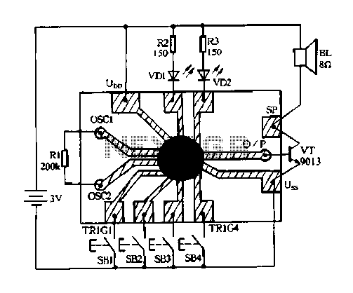
Constantly changing light and sound analog controller circuit 04
Constantly changing light and sound analog controller circuit 04
The circuit designated as the "Constantly Changing Light and Sound Analog Controller Circuit 04" is designed to modulate both light and sound outputs in a dynamic manner. This type of circuit...

Digital Oil-Pressure Gauge
This gauge utilizes a sensor along with resistor R1 to generate a DC voltage that is proportional to oil pressure. Integrated circuits IC1 and IC2 form a two-digit digital voltmeter (DVM). Transistors Q1 and Q2 act as display selectors for...

Homemade Digital CALL-ID English Version
The reason for this project was to facilitate a quick installation for a local friend 10 km away, enabling the start of real-life testing to identify and resolve bugs and problems before releasing it to other users. The software is...

Birds singing analog signal generator circuit
The circuit illustrated is an analog signal generator designed to produce a chirping sound, simulating birds singing. It employs six CD4069 inverters to create three oscillators, with two of them functioning as ultra-low frequency oscillators. The oscillation frequency is in...

Analog Voltage Camera-Image Tracker
By utilizing a low-cost RS-170 camera and this circuit, a voltage that indicates the position of an object within the camera's field of view is generated. IC2A and IC2B create a valid video gate that keeps IC3 in a reset...

Simple Digital Logic Probe Circuit
The design of the digital logic probe centers around a pair of complementary bipolar transistors, which, in this application, are used as electronic switches.
The digital logic probe is a diagnostic tool utilized for testing and analyzing digital circuits. The core...
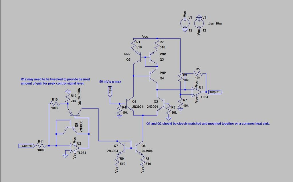
analog vocoder
This is the initial Instructable and the first attempt at a large electronics project. The circuit has been designed from scratch and is being made available.
The presented project involves the design of an electronic circuit that has been developed independently....