


Spectrometer
#spectrometer
#spectroscopy
#wavelength analysis
#optical measurement
#sensor
#data acquisition
#scientific instrumentation
#light analysis
#infrared
#nuclear magnetic resonance
Description: A spectrometer is an instrument used to view and analyze a spectrum of a specific characteristic of a substance, such as mass-to-charge values in mass spectrometry or wavelengths in absorption spectrometry, including techniques like nuclear magnetic resonance spectroscopy and infrared spectroscopy. A spectrophotometer, a type of spectrometer, specifically measures the intensity of electromagnetic radiation (light) and is distinct from other spectrometers like mass spectrometers. Spectrometers measure wavelengths of electromagnetic radiation that have interacted with a sample. The incident light can be reflected, absorbed, or transmitted through a sample, and the changes in the light during this interaction are characteristic of the sample. Spectrometers generally consist of three main components, which may vary based on the instrument's specific applications and resolution levels. These components typically generate electromagnetic radiation, narrow it to a specified range, and detect the resulting radiation after it interacts with the sample. There are two primary classes of radiation sources in spectrometry: continuum sources and line sources. Continuum sources, such as lamps or heated solids, emit a wide range of wavelengths that must be narrowed using a wavelength selection element to isolate the desired wavelength. Line sources, including lasers and specialized lamps, emit discrete wavelengths specific to the material of the lamp. Electrode lamps are sealed gas-filled chambers with electrodes that, when electrically excited, produce radiation at specific wavelengths associated with the gas used, such as argon, xenon, hydrogen, deuterium, or tungsten. Non-electrode lamps, which contain gas and metal, emit narrow radiation at desired wavelengths through ionization of the gas and energy transfer from the gas to the metal. Laser sources operate by activating a lasing material to produce and direct photons of specific energy, resulting in a coherent beam of light. Wavelength selection elements are non-dispersive materials that filter out unwanted wavelengths from the incident light, allowing only a specific range to pass. UV filters absorb UV radiation while transmitting other wavelengths, although modern spectrometers often utilize more precise filtering techniques, such as interference filters, which select wavelengths based on interference effects between incident and reflected radiation waves at material boundaries.
In the context of electronic schematics for a spectrometer, the design typically incorporates several key elements to ensure optimal performance in analyzing electromagnetic radiation. The power supply is crucial for providing stable voltage and current to the various components, including the light source, detectors, and signal processing units. The light source, whether a continuum or line source, is integrated into the schematic, ensuring that the output matches the required wavelengths for the specific application.
The optical path is designed to allow the incident light to interact with the sample effectively. This may include lenses or mirrors that focus the light onto the sample and collect the transmitted or reflected light for analysis. The use of optical fibers can also be included in the schematic to facilitate the transport of light between components while minimizing losses.
The wavelength selection components are critical and can be represented in the schematic as filter modules. These modules can include interference filters or other optical devices that selectively transmit the desired wavelengths while blocking others. The design must ensure that these elements are placed accurately within the optical path to maintain the integrity of the wavelength selection process.
The detector, which may be a photodiode, photomultiplier tube, or CCD sensor, is represented in the schematic as the final component in the optical chain. This component converts the incoming light into an electrical signal, which can then be processed and analyzed. The signal processing circuitry, including amplifiers, analog-to-digital converters, and microcontrollers, is essential for interpreting the data collected from the detector.
Overall, the electronic schematic of a spectrometer is a complex assembly of components designed to work in harmony to measure and analyze the electromagnetic spectrum accurately. Each element plays a vital role in ensuring that the spectrometer operates efficiently and produces reliable results.Strictly speaking, a spectrometer is any instrument used to view and analyze a range (or a spectrum) of a given characteristic for a substance (for example, a range of mass-to-charge values as in mass spectrometry), or a range of wavelengths as in absorption spectrometry like nuclear magnetic radiation spectroscopy or infrared spectroscopy). A sp ectrophotometer is a spectrometer that only measures the intensity of electromagnetic radiation (light) and is distinct from other spectrometers such as mass spectrometers. A spectrometer is typically used to measure wavelengths of electromagnetic radiation (light) that has interacted with a sample.
Incident light can be reflected off, absorbed by, or transmitted through a sample; the way the incident light changes during the interaction with the sample is characteristic of the sample. A spectrometer measures this change over a range of incident wavelengths (or at a specific wavelength).
There are three main components in all spectrometers; these components can vary widely between instruments for specific applications and levels of resolution. Very generally, these components produce the electromagnetic radiation, somehow narrows the electromagnetic radiation to a specified range, and then detect the resulting electromagnetic radiation after is has interacted with the sample.
There are two classes of radiation sources used in spectrometry: continuum sources and line sources. The former are usually lamps or heated solid materials that emit a wide range of wavelengths that must be narrowed greatly using a wavelength selection element to isolate the wavelength of interest. The latter sources include lasers and specialized lamps, that are designed to emit discrete wavelengths specific to the lamp`s material (Skoog).
Electrode lamps are constructed of a sealed, gas-filled chamber that has one or more electrodes inside. Electrical current is passed through the electrode, which causes excitation of the gas. This excitation produces radiation at a wavelength or a range of wavelengths, specific to the gas. Examples include argon, xenon, hydrogen or deuterium, and tungsten lamps, which emit radiation in the following ranges (Skoog).
There are also non-electrode lamps used as line sources that contain a gas and a piece of metal that will emit narrow radiation at the desired wavelength. Ionization of the gas occurs from radiation (usually in the radio or microwave frequencies). The metal atoms are then excited by a transfer of energy from the gas, thereby producing radiation at a very specific wavelength (Skoog).
Laser (an acronym for light amplification by stimulated emission of radiation) sources work by externally activating a lasing material so that photons of a specific energy are produced and aimed at the material (Skoog). This triggers photon production within the material, with more and more photons being produced as they reflect inside the material.
Because all the photons are of equal energy they are all in phase with each other so that energy (and wavelength) is isolated and enhanced. The photons are eventually focused into a narrow beam and then directed at the sample. Wavelength selection elements are non-dispersive materials that filter out the unwanted ranges of wavelengths from the incident light source, thereby allowing only a certain range of wavelengths to pass through.
For example, UV filters (as used on cameras) work by absorbing the UV radiation (100-400nm) but allowing other wavelengths to be transmitted. This type of filter is not common in modern spectrometers now that there are more precise elements available for narrowing the radiation.
There are also interference filters that select wavelengths by causing interference effects between the incident and reflected radiation waves at each of the material boundaries in the filter. The filter has layers of a dielectric material, semitransparent metallic films, and glass; the incident light is partitioned.
In the context of electronic schematics for a spectrometer, the design typically incorporates several key elements to ensure optimal performance in analyzing electromagnetic radiation. The power supply is crucial for providing stable voltage and current to the various components, including the light source, detectors, and signal processing units. The light source, whether a continuum or line source, is integrated into the schematic, ensuring that the output matches the required wavelengths for the specific application.
The optical path is designed to allow the incident light to interact with the sample effectively. This may include lenses or mirrors that focus the light onto the sample and collect the transmitted or reflected light for analysis. The use of optical fibers can also be included in the schematic to facilitate the transport of light between components while minimizing losses.
The wavelength selection components are critical and can be represented in the schematic as filter modules. These modules can include interference filters or other optical devices that selectively transmit the desired wavelengths while blocking others. The design must ensure that these elements are placed accurately within the optical path to maintain the integrity of the wavelength selection process.
The detector, which may be a photodiode, photomultiplier tube, or CCD sensor, is represented in the schematic as the final component in the optical chain. This component converts the incoming light into an electrical signal, which can then be processed and analyzed. The signal processing circuitry, including amplifiers, analog-to-digital converters, and microcontrollers, is essential for interpreting the data collected from the detector.
Overall, the electronic schematic of a spectrometer is a complex assembly of components designed to work in harmony to measure and analyze the electromagnetic spectrum accurately. Each element plays a vital role in ensuring that the spectrometer operates efficiently and produces reliable results.Strictly speaking, a spectrometer is any instrument used to view and analyze a range (or a spectrum) of a given characteristic for a substance (for example, a range of mass-to-charge values as in mass spectrometry), or a range of wavelengths as in absorption spectrometry like nuclear magnetic radiation spectroscopy or infrared spectroscopy). A sp ectrophotometer is a spectrometer that only measures the intensity of electromagnetic radiation (light) and is distinct from other spectrometers such as mass spectrometers. A spectrometer is typically used to measure wavelengths of electromagnetic radiation (light) that has interacted with a sample.
Incident light can be reflected off, absorbed by, or transmitted through a sample; the way the incident light changes during the interaction with the sample is characteristic of the sample. A spectrometer measures this change over a range of incident wavelengths (or at a specific wavelength).
There are three main components in all spectrometers; these components can vary widely between instruments for specific applications and levels of resolution. Very generally, these components produce the electromagnetic radiation, somehow narrows the electromagnetic radiation to a specified range, and then detect the resulting electromagnetic radiation after is has interacted with the sample.
There are two classes of radiation sources used in spectrometry: continuum sources and line sources. The former are usually lamps or heated solid materials that emit a wide range of wavelengths that must be narrowed greatly using a wavelength selection element to isolate the wavelength of interest. The latter sources include lasers and specialized lamps, that are designed to emit discrete wavelengths specific to the lamp`s material (Skoog).
Electrode lamps are constructed of a sealed, gas-filled chamber that has one or more electrodes inside. Electrical current is passed through the electrode, which causes excitation of the gas. This excitation produces radiation at a wavelength or a range of wavelengths, specific to the gas. Examples include argon, xenon, hydrogen or deuterium, and tungsten lamps, which emit radiation in the following ranges (Skoog).
There are also non-electrode lamps used as line sources that contain a gas and a piece of metal that will emit narrow radiation at the desired wavelength. Ionization of the gas occurs from radiation (usually in the radio or microwave frequencies). The metal atoms are then excited by a transfer of energy from the gas, thereby producing radiation at a very specific wavelength (Skoog).
Laser (an acronym for light amplification by stimulated emission of radiation) sources work by externally activating a lasing material so that photons of a specific energy are produced and aimed at the material (Skoog). This triggers photon production within the material, with more and more photons being produced as they reflect inside the material.
Because all the photons are of equal energy they are all in phase with each other so that energy (and wavelength) is isolated and enhanced. The photons are eventually focused into a narrow beam and then directed at the sample. Wavelength selection elements are non-dispersive materials that filter out the unwanted ranges of wavelengths from the incident light source, thereby allowing only a certain range of wavelengths to pass through.
For example, UV filters (as used on cameras) work by absorbing the UV radiation (100-400nm) but allowing other wavelengths to be transmitted. This type of filter is not common in modern spectrometers now that there are more precise elements available for narrowing the radiation.
There are also interference filters that select wavelengths by causing interference effects between the incident and reflected radiation waves at each of the material boundaries in the filter. The filter has layers of a dielectric material, semitransparent metallic films, and glass; the incident light is partitioned.

DIY computer infrared interface
A and B are two common contacts, along with an outline drawing and pin definitions. C refers to the shape of the infrared emission tube, including its pin definition and schematic symbol. CD4069 provides the pin definitions for the inverter...

Infrared transmitter II
The transmitter keyboard is organized as a scanned matrix consisting of 7 driver outputs and 7 sense inputs. The driver outputs, labeled DRVON to DRV6N, are open-drain n-channel transistors that remain conductive in standby mode. The 7 sense inputs, from...

Across The Track Infrared Detectors
This page presents information on infrared - Across The Track train detection circuits. The circuits are designed around the LM339 comparator chip and can use a wide assortment of matched infrared - emitter / detector pairs. The basic circuit shown...

IR remote control dimmer light circuit diagram
This is an infrared emission circuit diagram. The NE555 circuit generates a 40 kHz pulse, which is sent by the infrared emission control SE303 after being amplified by VT. The remote receiver and infrared dimming circuit are composed of the...

Implementing Infrared Object Detection
This document provides an overview of the components, schematic, software, and practical tips for utilizing infrared (IR) technology for object detection. The components employed are commonly found in consumer electronic remote controls and are readily available. An old television or...
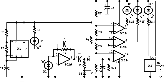
park aid schematics
IC1 operates as an oscillator that drives an infrared LED with pulses of 0.8 milliseconds at a frequency of 120 Hz, generating approximately 300 mA of peak current. Diodes D1 and D2 are aligned and positioned a few centimeters apart...
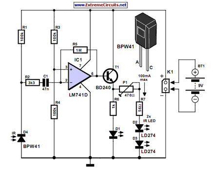
Simple Infrared Control Extender
Many consumer electronic devices such as television sets, VCRs, CD players, and DVD players utilize infrared remote control technology. In certain situations, it is beneficial to extend the range of these remote controls.
Infrared (IR) remote controls operate by emitting modulated...

ir detector circuit
The human eye is highly sensitive to visible light but cannot detect infrared (IR) radiation. This limitation can make it challenging to test or verify equipment that emits infrared radiation. An IR detector circuit has been developed to address this...

Infrared burglar alarm circuit schematic
The schematic for an infrared burglar alarm circuit is depicted in Figure 1. The infrared transmitter operates as a multivibrator with an oscillation frequency of 40 kHz, utilizing the NE555 integrated circuit (IC2), along with resistors R1 and R2 and...