


Tape monitor the direction of movement
#tape direction
#pulse generator
#D flip-flop
#decoding circuit
#LED display
#monitoring
#signal processing
#rectangular pulse
#T077
#direction detection

Description: The display circuit for tape direction is illustrated in the figure. It includes a rectangular pulse generator circuit, a D flip-flop (T077), a decoding circuit, and light-emitting diodes (LED1 to LED4), among other components. The rectangular pulse generator is composed of NAND gates YF1 to YF4, producing an output signal frequency of 1 to 3 Hz, which can be adjusted by changing the values of capacitor C1 and resistor R1. The T077 is configured as a counter that divides the output of the rectangular pulse generator by two. The decoding circuit, made up of NAND gates YF5 to YF8, controls the output signals to the light-emitting diodes, allowing LEDs 1 to 4 to illuminate and indicate the direction of tape movement. The direction of the illuminated LED depends on the polarity of the output pulse from the pulse generator. The output of NAND gate YF1 generates a positive pulse, while NAND gate YF3 produces a negative output. The flip-flop is connected to the PLAY button via pulse switches K1 to K3, which correspond to the REW function. When a function key is pressed, a trigger signal is generated, causing the light-emitting diodes to illuminate in a specific pattern that indicates the tape's movement direction. If the STOP key is pressed, the circuit enters a broken state, where only one pair of light-emitting diodes intermittently flashes at the oscillation frequency of the pulse generator, indicating that the recorder is powered on but the tape is not moving.
The circuit operates by utilizing a rectangular pulse generator as the central component, which generates a series of pulses at a specified frequency. The frequency can be fine-tuned through the selection of capacitor C1 and resistor R1, allowing for flexibility depending on the application requirements. The D flip-flop (T077) serves as a binary counter, effectively halving the frequency of the incoming pulse signal, which is essential for controlling the timing of the LED indicators.
The decoding circuit, constructed from additional NAND gates (YF5 to YF8), is responsible for interpreting the output of the D flip-flop and determining which LEDs should be activated based on the current state of the tape direction. The arrangement of the NAND gates ensures that the correct LED lights up according to the direction of the tape movement, whether it is playing forward or rewinding.
The mechanical switches (K1 to K3) are strategically placed to allow user interaction, enabling the selection of different playback functions. Each switch is connected to the circuit in such a way that pressing a button generates a unique trigger signal, which is then processed by the flip-flop and the NAND gates to control the corresponding LED output.
In the event that the STOP button is engaged, the circuit is designed to enter a standby state, where the LEDs exhibit a flashing behavior. This feature serves as a visual indicator to the user that, while the device is powered, it is not currently in motion, thereby providing clear feedback regarding the operational status of the tape recorder. As shown in FIG display circuit for the tape direction. The rectangular pulse generator circuit, D flip-flop (T077), the decoding circuit, the light emitting diode LED1 ~ LED4 and other components. By the rectangular pulse generator NAND gate YF1 ~ YF4 composition, the frequency of the output signal is 1 ~ 3Hz, changing C1, R1 adjustable corresponding frequency value. T077 connected as counter states, to signal a rectangular pulse generator output is divided by two. Decoding circuit consists of NAND gates YF5 ~ YF8, its output signal to control the light-emitting diode display, so that when the recorder is LED1 ~ LED4 turn light, indicating the tape running direction.
The moving direction of the light emitting point depends on the polarity of the output pulse of the pulse generator. Positive pulse circuit NAND gate YF1 output, the output of NAND gate YF3 negative, FF, PLAY button connected to the pulse switch K1 ~ K3 mechanically recorder respectively REW, which when pressed when a function key, the corresponding trigger signal will be added to the trigger, the light emitting diode emitting in the appropriate form, showing the direction of movement of the tape.
If you press the STOP key to display the state of the circuit is broken, only one pair of light-emitting diodes to the oscillation frequency of the pulse generator intermittently flashing, indicating that although the recorder is turned on, but the tape does not move.
The circuit operates by utilizing a rectangular pulse generator as the central component, which generates a series of pulses at a specified frequency. The frequency can be fine-tuned through the selection of capacitor C1 and resistor R1, allowing for flexibility depending on the application requirements. The D flip-flop (T077) serves as a binary counter, effectively halving the frequency of the incoming pulse signal, which is essential for controlling the timing of the LED indicators.
The decoding circuit, constructed from additional NAND gates (YF5 to YF8), is responsible for interpreting the output of the D flip-flop and determining which LEDs should be activated based on the current state of the tape direction. The arrangement of the NAND gates ensures that the correct LED lights up according to the direction of the tape movement, whether it is playing forward or rewinding.
The mechanical switches (K1 to K3) are strategically placed to allow user interaction, enabling the selection of different playback functions. Each switch is connected to the circuit in such a way that pressing a button generates a unique trigger signal, which is then processed by the flip-flop and the NAND gates to control the corresponding LED output.
In the event that the STOP button is engaged, the circuit is designed to enter a standby state, where the LEDs exhibit a flashing behavior. This feature serves as a visual indicator to the user that, while the device is powered, it is not currently in motion, thereby providing clear feedback regarding the operational status of the tape recorder. As shown in FIG display circuit for the tape direction. The rectangular pulse generator circuit, D flip-flop (T077), the decoding circuit, the light emitting diode LED1 ~ LED4 and other components. By the rectangular pulse generator NAND gate YF1 ~ YF4 composition, the frequency of the output signal is 1 ~ 3Hz, changing C1, R1 adjustable corresponding frequency value. T077 connected as counter states, to signal a rectangular pulse generator output is divided by two. Decoding circuit consists of NAND gates YF5 ~ YF8, its output signal to control the light-emitting diode display, so that when the recorder is LED1 ~ LED4 turn light, indicating the tape running direction.
The moving direction of the light emitting point depends on the polarity of the output pulse of the pulse generator. Positive pulse circuit NAND gate YF1 output, the output of NAND gate YF3 negative, FF, PLAY button connected to the pulse switch K1 ~ K3 mechanically recorder respectively REW, which when pressed when a function key, the corresponding trigger signal will be added to the trigger, the light emitting diode emitting in the appropriate form, showing the direction of movement of the tape.
If you press the STOP key to display the state of the circuit is broken, only one pair of light-emitting diodes to the oscillation frequency of the pulse generator intermittently flashing, indicating that although the recorder is turned on, but the tape does not move.

Simple Pulse Generator
A pulse generator typically allows control over the pulse repetition rate, pulse width, pulse delay, and pulse amplitude. More advanced pulse generators may also enable adjustments to the rise time and fall time of the pulses. The delay of a...
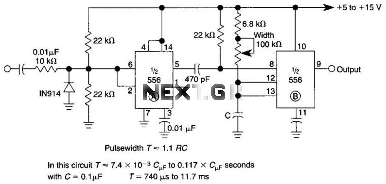
Pulse Generator Circuit
By utilizing a 556 dual timer, with IC1A functioning as a waveshaper and IC1B as a pulse generator, a pulse width range of 10:1 can be achieved. This circuit can be triggered using a sine wave.
The circuit operates on the...
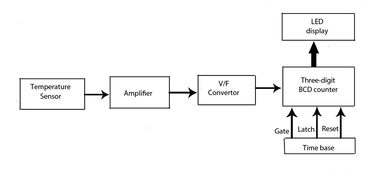
Advanced LED Temperature Indicator
This verified project provides an idea, circuit, and operation of the LED display temperature indicator. It features a digital temperature indicator utilizing a voltage-to-frequency (V/F) converter, along with various electronic projects.
The LED display temperature indicator is designed to provide a...

Pulse Generator circuit
A simple pulse generator with a variable duty cycle and frequency is often useful in the lab to trigger or test other devices, such as a servo with a frequency of 50 Hz and pulses between 1 and 2 ms....

Pulse Generator
This circuit is quite effective for testing or operating counters and stepping relays, as it eliminates the need for manually setting a switch for the desired number of pulses. By pressing the appropriate switches S1 to S9, one can generate...

Fast Low Duty-Cycle Pulse Oscillator
This simple and symmetrical free-running generator has a 50-ohm output impedance, a pulse width of 100 ns, and complementary outputs that swing from ground to the power supply voltage. It operates within a power supply range of less than 1...

High-speed control scheme LED display screen circuit diagram and principle
This document outlines the theory behind a high-speed control scheme for an LED display screen circuit. The circuit utilizes the MCS51 series microcontroller to manage the LED display. A 62512 random access memory (RAM) is employed for data storage, holding...

Pulse Generator With Variable Duty Cycle Circuit
This pulse generator utilizes a single integrated circuit (IC) and six passive components to achieve a frequency range of 400 to 4000 Hz, with an adjustable duty cycle ranging from 1% to 99%. The circuit employs a threshold detector (ICA)...

Pulse Generator Produces 3-Phase Output
This is a schematic diagram of a three-phase pulse generator circuit. This circuit produces a three-phase overlapped output similar to a three-phase AC power line.
The three-phase pulse generator circuit is designed to create three-phase output signals that are phase-shifted by...