


Test Instruments
#vacuum tube voltmeter
#digital multimeter
#high input impedance
#electrical measurements
#circuit testing
#VTVM
#DMM
#impedance matching
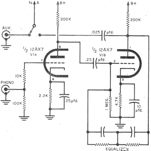
Description: Before the introduction of FET-input digital multimeters (DMMs), the vacuum tube voltmeter (VTVM) was the primary instrument used when high input impedance was necessary. High input impedance is crucial for measuring high impedance circuits to avoid loading the circuit under test, which could lead to inaccurate results. For example, when measuring the voltage across a 100 kΩ resistor in series with a 50 kΩ resistor, if the voltmeter has a 100 kΩ input impedance, the parallel combination of the two resistances results in 50 kΩ. With a supply voltage of 3 volts, the voltage across the 100 kΩ resistor would be 2 volts, but the voltmeter would read only 1.5 volts. Conversely, if the voltmeter's input impedance were 10 MΩ, the parallel resistance would be approximately 99 kΩ, introducing a minimal error. The sensitivity of a measuring instrument significantly impacts the circuit under test. Using a low ohm voltmeter in a high impedance circuit can lead to inaccurate measurements. The VTVM excels in measuring signal voltage in hi-fi amplifiers, allowing for accurate a.c. signal voltage measurements without distortion, even in the presence of d.c. signals. Signal voltage is critical as it is what the magnetic phono cartridge or tuner supplies to the amplifier, which amplifies these weak signals into stronger currents for speaker movement. Analyzing the signal voltage at various stages of amplification provides insight into the contributions of each tube in the circuit.
The Eico HF-12 amplifier circuit serves as an example for testing. It is well-designed and shares circuit configurations with other amplifiers of similar or greater wattage, making it applicable for various models. The schematic of the HF-12 includes a preamplifier stage utilizing a 12AX7 tube (V1) with plate-to-grid feedback equalization. Following this, a tone control circuit is constructed using the two triodes of a 12AU7 tube (V2), which feeds into a modified Williamson-type power amplifier. This power amplifier consists of a dual triode driver/inverter (V3) and a pair of push-pull pentode outputs (V4 and V5). This configuration allows for comprehensive testing and measurement of signal voltages at each stage of amplification, providing valuable insights into the performance characteristics of the amplifier.Prior to the advent of FET-input digital multimeters (DMMs), the vacuum tube voltmeter (VTVM) was the primary instrument for use when high input impedance was required. For the newcomer to electrical measurements, high input impedance for the measuring instrument is needed when measuring high impedance circuits so as not to load down the circuit under test and cause an erroneous result.
For instance, suppose you are trying to measure the voltage across a 100 k © resistor that is in series with a 50 k © and your voltmeter has a 100 k © input impedance. The parallel combination of the two 100 k © resistances (resistor and voltmeter) is 50 k ©. If the supply voltage is 3 volts, the voltage across the 100 k © resistor would actually be 2 volts, but with the voltmeter across it, the reading would be 1.
5 volts. If the input impedance of the voltmeter was 10 M © instead, the parallel resistance across the 100 k © resistor would be about 99 k ©, which would only introduce a very small error. I`ll try to get the previous 5 parts of this article. In checking out the vacuum-tube voltmeter in the last two installments of Test Instruments, we discovered that one of the most important reasons for using a VTVM was "sensitivity.
" In practical terms, the sensitivity of a measuring instrument determines how it affects the circuit under test. Using a low ohms/voltmeter in a high impedance circuit is like trying to gauge a person`s strength with a 10-ton weight.
What you`re trying to measure crumbles under the load. One area where the VTVM comes into its own is in signal voltage measurement in hi-fi amplifiers. For not only can the VTVM measure the a. c. signal voltage without knocking it to its knees, but it will perform the measurement in the presence of d. c. at any frequency in the amplifier`s range. If there`s a large enough signal at a tube pin - your VTVM will read it. What`s so important about signal voltage Well, signal voltage is what your magnetic phono cartridge (or tape head or tuner) supplies to your amplifier to be passed on to your speaker.
Your amplifier is not just a passive element, but is more like an electronic Charles Atlas that builds up the weakling input signals into the sort of powerful currents that can move, if not mountains, at least speaker cones. If we take a look at the signal voltage at each stage of its development, we can get a good idea of exactly what contribution is made by each tube in the circuit.
Fig. 14. Eico HF-12 amplifier circuit broken down into its separate sections for the purpose of discussion in the text. Reading from top to bottom, sections are: preamplifier, tone control and power amplifier. The Guinea Pig. Let`s take a standard hi-fi amplifier as our guinea pig and put it through its paces using an audio generator to supply the signal voltage and a VTVM to measure it.
The amplifier we will work with - the Eico HF-12 - is not only well designed but, in addition, has the advantage for us that it shares a number of its circuit configurations with amplifiers of similar and higher wattage. The same tests and techniques we use to check out the Eico unit can therefore also be applied to other mono and stereo amplifiers.
Let`s take a quick look at the HF-12`s schematic in Fig. 14. The preamp stage uses a 12AX7 tube (V1) with plate-to-grid feedback equalization. The two triodes of a 12AU7 tube (V2) comprise the Baxandall negative feedback tone control circuit which in turn feeds a modified Williamson type power amplifier comprising a dual triode driver/inverter (V3) and a pair of push-pull pentode outputs (V4 and V5). For the tests we ha
The Eico HF-12 amplifier circuit serves as an example for testing. It is well-designed and shares circuit configurations with other amplifiers of similar or greater wattage, making it applicable for various models. The schematic of the HF-12 includes a preamplifier stage utilizing a 12AX7 tube (V1) with plate-to-grid feedback equalization. Following this, a tone control circuit is constructed using the two triodes of a 12AU7 tube (V2), which feeds into a modified Williamson-type power amplifier. This power amplifier consists of a dual triode driver/inverter (V3) and a pair of push-pull pentode outputs (V4 and V5). This configuration allows for comprehensive testing and measurement of signal voltages at each stage of amplification, providing valuable insights into the performance characteristics of the amplifier.Prior to the advent of FET-input digital multimeters (DMMs), the vacuum tube voltmeter (VTVM) was the primary instrument for use when high input impedance was required. For the newcomer to electrical measurements, high input impedance for the measuring instrument is needed when measuring high impedance circuits so as not to load down the circuit under test and cause an erroneous result.
For instance, suppose you are trying to measure the voltage across a 100 k © resistor that is in series with a 50 k © and your voltmeter has a 100 k © input impedance. The parallel combination of the two 100 k © resistances (resistor and voltmeter) is 50 k ©. If the supply voltage is 3 volts, the voltage across the 100 k © resistor would actually be 2 volts, but with the voltmeter across it, the reading would be 1.
5 volts. If the input impedance of the voltmeter was 10 M © instead, the parallel resistance across the 100 k © resistor would be about 99 k ©, which would only introduce a very small error. I`ll try to get the previous 5 parts of this article. In checking out the vacuum-tube voltmeter in the last two installments of Test Instruments, we discovered that one of the most important reasons for using a VTVM was "sensitivity.
" In practical terms, the sensitivity of a measuring instrument determines how it affects the circuit under test. Using a low ohms/voltmeter in a high impedance circuit is like trying to gauge a person`s strength with a 10-ton weight.
What you`re trying to measure crumbles under the load. One area where the VTVM comes into its own is in signal voltage measurement in hi-fi amplifiers. For not only can the VTVM measure the a. c. signal voltage without knocking it to its knees, but it will perform the measurement in the presence of d. c. at any frequency in the amplifier`s range. If there`s a large enough signal at a tube pin - your VTVM will read it. What`s so important about signal voltage Well, signal voltage is what your magnetic phono cartridge (or tape head or tuner) supplies to your amplifier to be passed on to your speaker.
Your amplifier is not just a passive element, but is more like an electronic Charles Atlas that builds up the weakling input signals into the sort of powerful currents that can move, if not mountains, at least speaker cones. If we take a look at the signal voltage at each stage of its development, we can get a good idea of exactly what contribution is made by each tube in the circuit.
Fig. 14. Eico HF-12 amplifier circuit broken down into its separate sections for the purpose of discussion in the text. Reading from top to bottom, sections are: preamplifier, tone control and power amplifier. The Guinea Pig. Let`s take a standard hi-fi amplifier as our guinea pig and put it through its paces using an audio generator to supply the signal voltage and a VTVM to measure it.
The amplifier we will work with - the Eico HF-12 - is not only well designed but, in addition, has the advantage for us that it shares a number of its circuit configurations with amplifiers of similar and higher wattage. The same tests and techniques we use to check out the Eico unit can therefore also be applied to other mono and stereo amplifiers.
Let`s take a quick look at the HF-12`s schematic in Fig. 14. The preamp stage uses a 12AX7 tube (V1) with plate-to-grid feedback equalization. The two triodes of a 12AU7 tube (V2) comprise the Baxandall negative feedback tone control circuit which in turn feeds a modified Williamson type power amplifier comprising a dual triode driver/inverter (V3) and a pair of push-pull pentode outputs (V4 and V5). For the tests we ha

DMM-ProfiLab 4.0
The DMM-ProfiLab-Software allows you to develop any measuring technology projects based upon digital multimeters: A simple curve plotter or a complex measuring technology project. By the integrated support of relay cards you are not only able to read and process...

rf Can I merge two impedance matching circuits
Place the transceiver and the chip antenna very close together, eliminating the need for a 50-ohm transmission line. If this is the case, can the two matching circuits be merged into one to reduce the component count?
To create an efficient...
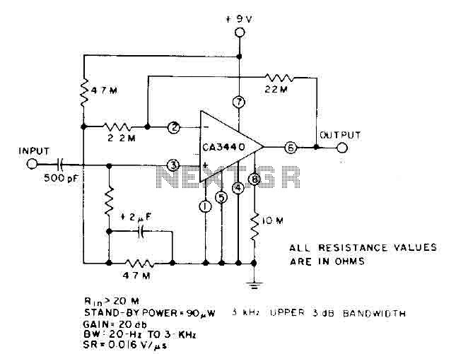
High input impedance amplifier CA3440
This circuit utilizes the low power leakage, high input impedance, frequency response, and capacitance characteristics of the CA3440 operational amplifier. Only one input coupling capacitor of 500 pF is required to attain a -3 dB low frequency response at 20...

Add a thermometer to your digital multimeter
A digital multimeter is a highly versatile instrument that integrates multiple measurement functions within a single unit. Typically, a multimeter encompasses the functionalities of a variable-range ohmmeter, voltmeter, and ammeter, with some models also capable of testing diodes and transistors....

Designing Simple Digital Multimeter
The following circuit illustrates the design of a simple digital multimeter circuit diagram. This circuit employs the ADD3501. Features include the combination of voltage measurements, among others.
The circuit design for a simple digital multimeter utilizing the ADD3501 integrates several essential...

digital multimeter for your car
A digital tachometer and speedometer utilizing a seven-segment display was initially attempted but not successfully implemented due to overcrowding of integrated circuits (ICs) and components. An LED tachometer was successfully constructed later, followed by the development of an LED speedometer...

dmm fuse protector
Typically, the input protection fuse of a digital multimeter (DMM) will blow during a demonstration or an exciting phase of construction work. Spare fuses are often difficult to find, and if available, they take a considerable amount of time to...
DMM-ProfiLab 4.0
The DMM-ProfiLab-Software allows you to develop any measuring technology projects based upon digital multimeters: A simple curve plotter or a complex measuring technology project. By the integrated support of relay cards you are not only able to read and process...