


THREE RANGE LIGHT METER
#light meter
#Clairex 905HN
#differential amplifier
#calibration
#battery check
#light-dependent resistor
#meter
#voltage check
#sensor circuit
#measurement

Description: This circuit utilizes a probe that contains a Clairex 905HN light-dependent resistance element, which is connected to a DC differential amplifier. The amplifier drives a meter with a specially calibrated scale. The article outlines the calibration procedure. A switching circuit is included to continuously monitor the voltage of a 22.5-V battery. If the 4.5-V battery is low, full-scale adjustment cannot be achieved. Resistors with values specified in the article are sequentially connected to the terminals of the photocell jack P1 for calibration, allowing for a linear scale reading.
The described circuit functions as a photo exposure meter, designed to provide accurate light measurements. The Clairex 905HN light-dependent resistor (LDR) serves as the sensor, responding to varying light levels by changing its resistance. This change is detected by the DC differential amplifier, which amplifies the signal for improved readability on the meter.
The calibration procedure outlined in the article is critical for ensuring that the meter provides accurate readings across its scale. This process involves connecting specific resistors to the photocell jack P1, which allows the user to adjust the meter's response to light levels, ensuring that the readings are linear and proportional to the light intensity.
The inclusion of a switching circuit to monitor the 22.5-V battery is an essential feature, as it ensures that the circuit remains functional and accurate. If the 4.5-V battery, which may be used for other components, is low, the circuit will not be able to achieve a full-scale adjustment, potentially leading to inaccurate readings. Therefore, maintaining the battery voltage is crucial for the reliability of the meter.
In summary, this electronic schematic is designed for accurate light measurement, with a focus on calibration and battery monitoring. The integration of the Clairex 905HN light-dependent resistance element with a DC differential amplifier and a calibrated meter provides a robust solution for photo exposure measurement, making it suitable for various applications in photography and lighting analysis.Uses probe containing Clairex 905HN light-dependent resistance element, connected to DC differential amplifier driving meter having specially calibrated scale. Article gives calibration procedure. Switching circuit provides constant check on voltage of 22. 5-V battery. If 4. 5-V battery is low full-scale adjustment cannot be made Resistors having values specified in article are connected in turn to terminals of photocell jack P1 for calibration that gives linear scale reading. -J. L. Mills, Jr. , Light Right Do-It-Yourself Photo Exposure Meter, 73 Magazine, Sept. 1978, p 204 206 and 208-211.
The described circuit functions as a photo exposure meter, designed to provide accurate light measurements. The Clairex 905HN light-dependent resistor (LDR) serves as the sensor, responding to varying light levels by changing its resistance. This change is detected by the DC differential amplifier, which amplifies the signal for improved readability on the meter.
The calibration procedure outlined in the article is critical for ensuring that the meter provides accurate readings across its scale. This process involves connecting specific resistors to the photocell jack P1, which allows the user to adjust the meter's response to light levels, ensuring that the readings are linear and proportional to the light intensity.
The inclusion of a switching circuit to monitor the 22.5-V battery is an essential feature, as it ensures that the circuit remains functional and accurate. If the 4.5-V battery, which may be used for other components, is low, the circuit will not be able to achieve a full-scale adjustment, potentially leading to inaccurate readings. Therefore, maintaining the battery voltage is crucial for the reliability of the meter.
In summary, this electronic schematic is designed for accurate light measurement, with a focus on calibration and battery monitoring. The integration of the Clairex 905HN light-dependent resistance element with a DC differential amplifier and a calibrated meter provides a robust solution for photo exposure measurement, making it suitable for various applications in photography and lighting analysis.Uses probe containing Clairex 905HN light-dependent resistance element, connected to DC differential amplifier driving meter having specially calibrated scale. Article gives calibration procedure. Switching circuit provides constant check on voltage of 22. 5-V battery. If 4. 5-V battery is low full-scale adjustment cannot be made Resistors having values specified in article are connected in turn to terminals of photocell jack P1 for calibration that gives linear scale reading. -J. L. Mills, Jr. , Light Right Do-It-Yourself Photo Exposure Meter, 73 Magazine, Sept. 1978, p 204 206 and 208-211.

Common mode input voltage of the differential amplifier circuit diagram up l00V
Common mode input voltage up to a difference of 100V enlarged circuit diagram.
The circuit diagram described features a design capable of handling a common mode input voltage with a differential range of up to 100V. Such a configuration is essential...

A constant current source of the differential amplifier circuit
A constant current source is utilized in the differential amplifier circuit, which includes an emitter resistor. In this configuration, an increase in the output voltage (Ua) is not desirable. To ensure that Ua remains stable, the supply voltage (Ucc) can...

ProfiLab-Expert 4.0
The ProfiLab-Expert software allows you to develop your own digital or analogue measuring technology projects. It doesn't matter if you want to create analogue measurements or digital controls - you can realize it all. And for all this you don't...

Differential amplifier circuit four connection methods and characteristics of comparison c
Differential amplifier circuit with four connection methods and characteristics for comparison. The circuit exhibits magnification with a single tube when symmetrical. Additionally, CMRR (Common Mode Rejection Ratio) is adapted from single-ended input to a double-ended output.
The differential amplifier is a...

Differential amplifier circuit has a constant current source
The differential amplifier circuit features a constant current source.
The differential amplifier is a fundamental building block in analog electronics, utilized for amplifying the difference between two input voltages while rejecting any signals that are common to both inputs. Central to...

Digital-ProfiLab 4.0
Digital-ProfiLab was designed for measurement and control applications, combining features like circuit and logic simulation, front panel design, and hardware control to one powerful tool. Incoming signals from external devices may be processed and displayed. A circuit editor is used...
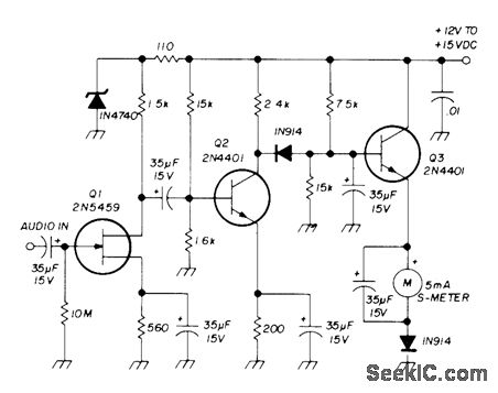
5 mA S METER
The circuit designed for a 5 mA meter movement utilizes a two-stage voltage amplifier comprising transistors Q1 and Q2. An emitter-follower output stage, represented by transistor Q3, functions as an impedance-matching stage. The audio frequency (AF) input for an S-9...
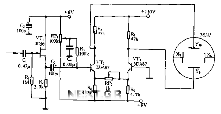
Application of the differential amplifier circuit in a simple small oscilloscope
Application of the differential amplifier circuit in a simple small oscilloscope.
The differential amplifier circuit is a crucial component in the design of a simple small oscilloscope. This circuit is designed to amplify the difference between two input voltage signals while...

Light meter
This light meter features an eight-decade range. Bias current compensation enables an input current resolution of better than ±2 pA over a temperature range of 15 °C to 55 °C.
The light meter is designed to measure luminous intensity across a...