


Tiny pH-meter
#pH-meter
#measurement
#instrumentation
#PSU
#PCB
#college
#educational
#reliability
#small form factor

Description: This tiny pH-meter is very tiny: 11cm2 including the PSU circuit! I built it for the College Saint Pierre a few years ago. It is based on a circuit developed at the Facultes Notre-Dame de la Paix, Namur, Belgium. I modified several components to allow a smaller power supply (+/-5V instead of +/-12V) which could be used to power the display unit. I also spent some time fitting everything on a very small PCB, just for the fun of it (and also because PCBs are sold per cm2 of surface). At this time about 30 have been built and used for several years during college classes, demonstrating their reliability. More: The circuit input is pin 15 of K1. The probe signal enters IC1 via an RC circuit designed to allow only relatively slow signal variations (and avoid getting parasite HF signals). IC1 is a CMOS op-amp and thus has a very high impedance. The gain of IC1 is
The pH meter circuit is designed to measure the acidity or alkalinity of a solution through a glass electrode probe. The compact design, measuring only 11 cm², incorporates a power supply unit (PSU) that operates at a reduced voltage of +/-5V, making it suitable for portable applications and reducing power consumption compared to traditional +/-12V systems.
The circuit begins with the pH probe connected to pin 15 of connector K1. The probe generates a voltage that corresponds to the pH level of the solution. This signal is then fed into IC1, a CMOS operational amplifier (op-amp), which is chosen for its high input impedance. This characteristic is crucial as it prevents loading the probe, ensuring accurate readings.
To filter out high-frequency noise that could interfere with the measurement, the signal passes through an RC (resistor-capacitor) circuit before reaching the op-amp. This low-pass filter configuration allows only slow variations in the signal to be processed, effectively eliminating unwanted high-frequency noise or parasitic signals that could skew results.
The gain of IC1 is set to amplify the weak signal from the pH probe to a usable level for further processing or display. The design ensures that the op-amp operates within its optimal range, preserving the integrity of the pH measurements.
The compact PCB layout has been optimized for minimal space usage, which is a significant consideration given that PCB costs are often determined by surface area. This design has proven reliable over several years of usage in educational settings, demonstrating its effectiveness in teaching and practical applications. Overall, this pH meter represents a blend of innovative engineering and practical design, making it a valuable tool for both educational and experimental purposes.This tiny pH-meter is very tiny: 11cm2 including the PSU circuit! I built it for the College Saint Pierre a few years ago. It is based on a circuit developped at the Facultes Notre-Dame de la Paix, Namur, Belgium. I modified several components to allow a smaller power supply (+/-5V instead of +/-12V) which could be used to power the display unit. I also spent `some time` fitting everything on a very small PCB, just for the fun of it (and also because PCBs are sold per cm2 of surface).
At this time about 30 have been built and used for several years during college classes, demonstrating their reliability. The circuit input is pin 15 of K1. The probe signal enters IC1 via an RC circuit designed to allow only relatively slow signal variations (and avoid getting parasite HF signals). IC1 is a CMOS op-amp and thus has a very high impedance. The gain of IC1 is
The pH meter circuit is designed to measure the acidity or alkalinity of a solution through a glass electrode probe. The compact design, measuring only 11 cm², incorporates a power supply unit (PSU) that operates at a reduced voltage of +/-5V, making it suitable for portable applications and reducing power consumption compared to traditional +/-12V systems.
The circuit begins with the pH probe connected to pin 15 of connector K1. The probe generates a voltage that corresponds to the pH level of the solution. This signal is then fed into IC1, a CMOS operational amplifier (op-amp), which is chosen for its high input impedance. This characteristic is crucial as it prevents loading the probe, ensuring accurate readings.
To filter out high-frequency noise that could interfere with the measurement, the signal passes through an RC (resistor-capacitor) circuit before reaching the op-amp. This low-pass filter configuration allows only slow variations in the signal to be processed, effectively eliminating unwanted high-frequency noise or parasitic signals that could skew results.
The gain of IC1 is set to amplify the weak signal from the pH probe to a usable level for further processing or display. The design ensures that the op-amp operates within its optimal range, preserving the integrity of the pH measurements.
The compact PCB layout has been optimized for minimal space usage, which is a significant consideration given that PCB costs are often determined by surface area. This design has proven reliable over several years of usage in educational settings, demonstrating its effectiveness in teaching and practical applications. Overall, this pH meter represents a blend of innovative engineering and practical design, making it a valuable tool for both educational and experimental purposes.This tiny pH-meter is very tiny: 11cm2 including the PSU circuit! I built it for the College Saint Pierre a few years ago. It is based on a circuit developped at the Facultes Notre-Dame de la Paix, Namur, Belgium. I modified several components to allow a smaller power supply (+/-5V instead of +/-12V) which could be used to power the display unit. I also spent `some time` fitting everything on a very small PCB, just for the fun of it (and also because PCBs are sold per cm2 of surface).
At this time about 30 have been built and used for several years during college classes, demonstrating their reliability. The circuit input is pin 15 of K1. The probe signal enters IC1 via an RC circuit designed to allow only relatively slow signal variations (and avoid getting parasite HF signals). IC1 is a CMOS op-amp and thus has a very high impedance. The gain of IC1 is

ProfiLab-Expert 4.0
The ProfiLab-Expert software allows you to develop your own digital or analogue measuring technology projects. It doesn't matter if you want to create analogue measurements or digital controls - you can realize it all. And for all this you don't...

13.8V 20A power supply
This power supply unit (PSU) is specifically designed for high-current ham radio transceivers. It safely provides approximately 20 Amps at 13.8V. For lower current applications, a separate current-limiting output is available, capable of 15 mA up to a total of...
ProfiLab-Expert 4.0
The ProfiLab-Expert software allows you to develop your own digital or analogue measuring technology projects. It doesn't matter if you want to create analogue measurements or digital controls - you can realize it all. And for all this you don't...

Instrumentation circuit
The mechanical chassis prototype, as illustrated in the accompanying image, was constructed using two materials: foam and aluminum. Foam was selected for its ease of manipulation, while aluminum was chosen for its excellent strength-to-weight ratio. The prototype features a rotary...

ALTIUM DESIGNER
The PCB is at the center of any electronic product. Literally, the enclosure surrounds the board, and figuratively, all the mathematics, the science, the software, these all run on the board. That’s why the PCB is at the center of...

Board making technique
When designing a printed circuit board (PCB), a technique is employed to create a broad grounding pattern separate from the signal and power patterns. This approach is particularly useful for high-frequency circuits or when attempting to mitigate external noise interference....
RealView 2.0
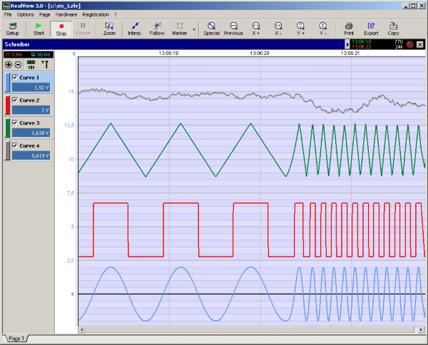
RealView is a measurement application, which records and plots measured values from analogue hardware devices in real-time. Several curves can be plotted into a single diagram. Several diagrams can be arranged on one or more pages if necessary. Plot options...

Advances in Measurement & Sensor Tech
This issue features articles on various measurement and sensor-related embedded design projects. Readers are encouraged to attempt similar projects and share their results. Starting on page 14, Petre Tzvetanov Petrov describes a multilevel audible logical probe design. Petrov notes that...

9 Volt 2 Amp PSU with 78S09
The circuit will work without the extra components, but for reverse polarity protection a 1N5400 diode is provided at the input, extra smoothing being provided by C1. The output stage includes C2 for extra filtering, if powering a logic circuit...