


Voltage Gauge
#voltage gauge
#A/D converter
#RCA CA3162E
#BCD output
#display decoder
#measurement
#instrumentation
#12-bit

Description: This circuit utilizes an RCA CA3162E (IC2) analog-to-digital (A/D) converter. The converter provides a 12-bit output in binary-coded decimal (BCD), which is sent to the display driver (IC1). A +5 V supply is derived from IC1. Resistor R17 is adjusted to zero, while resistor R11 is calibrated to ensure the accuracy of the gauge unit. The displays employed are of the common cathode type, and no limiting resistors are required due to the constant current output drivers. Resistors R15 and R16 are used to sample the applied voltage, typically ranging from 8 to 18 V. An LED (LED1) is incorporated to illuminate the gauge legend, indicating measurements such as voltage and temperature.
The circuit employs the RCA CA3162E A/D converter, which is integral for converting analog signals into digital format. This component is particularly notable for its 12-bit resolution, allowing for precise representation of the input signals. The BCD output from the A/D converter is interfaced with a display driver (IC1), which is responsible for driving the display elements.
The power supply for the circuit is established through IC1, which outputs a regulated +5 V necessary for the operation of the A/D converter and other associated components. The calibration of the gauge unit is critical for accurate readings; thus, R11 is adjustable to ensure that the output reflects the true value of the measured parameter. Meanwhile, R17 is set to zero, serving as a baseline for the calibration process.
The choice of common cathode displays simplifies the design, as it eliminates the need for additional limiting resistors. This is advantageous because the output drivers are designed to provide a constant current, ensuring consistent brightness and clarity of the display without the risk of damage from overcurrent conditions.
The resistors R15 and R16 play a vital role in voltage sensing. By sampling the applied voltage, which typically falls within the range of 8 to 18 V, these resistors allow the circuit to monitor and display the relevant measurements accurately. The inclusion of LED1 enhances the user interface by providing visual cues through illumination, indicating the parameters being measured, such as voltage and temperature. This design approach not only improves functionality but also enhances user experience by making the gauge readings easily interpretable. This circuit uses an RCA CA3162E (IC2) A/D converter. This converter has 12-bit output (BCD) which is sent to display decoder driver IC1. +5 V is obtained from IC1. R17 adjusts to 0 and Rll should be set to produce correct calibration of gauge unit. Displays are common cathode types. No limiting resistors are necessary because the output drivers are constant current. R15 and R16 sample the applied voltage (usually 8 to 18 V). LED1 is used to illuminate the gauge legend (Volts, Temp, etc.).
The circuit employs the RCA CA3162E A/D converter, which is integral for converting analog signals into digital format. This component is particularly notable for its 12-bit resolution, allowing for precise representation of the input signals. The BCD output from the A/D converter is interfaced with a display driver (IC1), which is responsible for driving the display elements.
The power supply for the circuit is established through IC1, which outputs a regulated +5 V necessary for the operation of the A/D converter and other associated components. The calibration of the gauge unit is critical for accurate readings; thus, R11 is adjustable to ensure that the output reflects the true value of the measured parameter. Meanwhile, R17 is set to zero, serving as a baseline for the calibration process.
The choice of common cathode displays simplifies the design, as it eliminates the need for additional limiting resistors. This is advantageous because the output drivers are designed to provide a constant current, ensuring consistent brightness and clarity of the display without the risk of damage from overcurrent conditions.
The resistors R15 and R16 play a vital role in voltage sensing. By sampling the applied voltage, which typically falls within the range of 8 to 18 V, these resistors allow the circuit to monitor and display the relevant measurements accurately. The inclusion of LED1 enhances the user interface by providing visual cues through illumination, indicating the parameters being measured, such as voltage and temperature. This design approach not only improves functionality but also enhances user experience by making the gauge readings easily interpretable. This circuit uses an RCA CA3162E (IC2) A/D converter. This converter has 12-bit output (BCD) which is sent to display decoder driver IC1. +5 V is obtained from IC1. R17 adjusts to 0 and Rll should be set to produce correct calibration of gauge unit. Displays are common cathode types. No limiting resistors are necessary because the output drivers are constant current. R15 and R16 sample the applied voltage (usually 8 to 18 V). LED1 is used to illuminate the gauge legend (Volts, Temp, etc.).

Digital-ProfiLab 4.0
Digital-ProfiLab was designed for measurement and control applications, combining features like circuit and logic simulation, front panel design, and hardware control to one powerful tool. Incoming signals from external devices may be processed and displayed. A circuit editor is used...
Digital-ProfiLab 4.0
Digital-ProfiLab was designed for measurement and control applications, combining features like circuit and logic simulation, front panel design, and hardware control to one powerful tool. Incoming signals from external devices may be processed and displayed. A circuit editor is used...
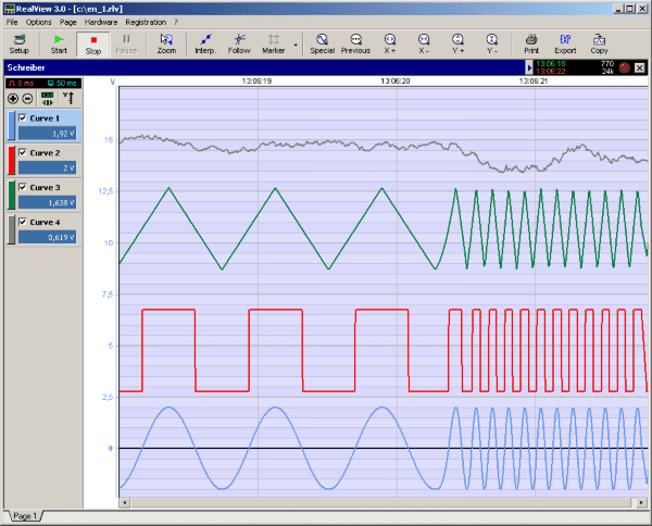
RealView 2.0
RealView is a measurement application, which records and plots measured values from analogue hardware devices in real-time. Several curves can be plotted into a single diagram. Several diagrams can be arranged on one or more pages if necessary. Plot options...

Simple A/D converter circuit with 2504
The time IO-bit conversion operates at 3.3 MHz with a clock signal. This converter utilizes a 2504 12-bit register in successive approximation mode, where the conversion signal for the short-cycle end is derived from the first bit utilized in the...

High Speed A/D converter 12-bit
This system performs a complete conversion of 12 bits in both unipolar and bipolar modes. The converter is accurate to ±12-bit LSB with a typical gain temperature coefficient of 10 ppm/°C. In unipolar mode, the system operates within a range...

The Comets Flame
The project aims to utilize a high-precision analog-to-digital (A/D) converter for data acquisition, followed by storing the collected data onto an SD flash memory card in a format compatible with Windows. The software for interfacing with the SD card has...

ICL7106 1/2 Digit LCD/LED Display A/D Converters
The Intersil ICL7106 and ICL7107 are high-performance, low-power, 3½ digit analog-to-digital (A/D) converters. They include seven-segment decoders, display drivers, a reference, and a clock. The ICL7106 is designed to interface with a liquid crystal display (LCD) and features a multiplexed...

A/D Board
An IBM PC can operate two 12-bit A/D converters via its printer port. The converters' serial outputs utilize only two of the printer port's eight data lines (DATA A OUT, DATA B OUT). The IBM PC's printer port does not...

LF356 composed of AD converter
An A/D converter transforms an analog signal into a digital format. Various circuit configurations exist, as illustrated in Figures 21-24, which depict the structure of an A/D converter. One practical circuit configuration utilizes the integrated circuit LF356.
The A/D converter is...