


beat frequency oscillator simple metal
#cmos4011
#oscillator
#metal detection
#reference oscillator
#search coil
#frequency
#DIY
#electronics project
#simple circuit
#versatile

Description: This design for a metal detector requires a variety of components and a few hours of work. Based on a CMOS 4011 integrated circuit, it is quite effective and versatile. The 250 kHz reference oscillator is constructed using two gates (U1/1 and U1/2), along with components C1, R1, and P1. The search oscillator utilizes only one gate (U1/3), two capacitors, and the search coil. The outputs from the two oscillators are connected to the fourth gate, which functions as a mixer and is filtered by C4. After assembly, headphones should be connected, and P1 should be turned slowly. The tone will decrease until it disappears. Continuing to turn P1 in the same direction will cause the tone to increase again. The point at which the tone is at its lowest and disappears is referred to as "zero beat." If it is not possible to achieve this zero beat with the full rotation of P1, it may be necessary to adjust the values for C1. After positioning P1 close to the zero beat point, the search coil should be moved near a metallic object. The tone should change based on the size and distance of the metal. It is important to note that the performance of this simple detector is not comparable to more advanced commercial products. It will only detect larger metallic objects at a short distance, while coins and smaller items will be much harder to locate.
This metal detector circuit utilizes a CMOS 4011 integrated circuit, which contains four NAND gates. The design begins with the construction of a 250 kHz reference oscillator, formed by two of these gates (U1/1 and U1/2), a resistor (R1), a capacitor (C1), and a potentiometer (P1) that allows for fine-tuning of the oscillation frequency. The second oscillator, which serves as the search oscillator, is created using one additional NAND gate (U1/3), two capacitors, and the search coil that acts as the sensing element.
The outputs from the reference and search oscillators are fed into the fourth NAND gate, which functions as a mixer. This gate combines the signals from both oscillators, and the output is filtered through capacitor C4 to eliminate unwanted frequencies, allowing only the desired signal to pass through.
Once the circuit is fully assembled, headphones are connected to the output to allow the user to hear the audio signal produced by the oscillators. The user then gradually adjusts the potentiometer P1. Initially, the tone produced will decrease until it reaches a point of silence, known as zero beat. This is a critical point for tuning the detector, as it indicates that the frequencies from both oscillators are aligned.
If the user cannot achieve a zero beat with the full range of P1, it may indicate that the capacitor C1 needs to be adjusted to alter the oscillation frequency. Once the zero beat is achieved, the search coil can be moved near metallic objects. The tone will vary based on the size and proximity of the metal detected. This circuit is designed for basic metal detection and is primarily effective for larger metallic objects, with limitations in detecting smaller items like coins at greater distances. Overall, this simple metal detector provides a foundational understanding of oscillation and signal mixing in electronic circuit design.This is a design of metal detector requires alone a scattering of apparatus and an evening`s work. Congenital about a cmos4011 IC, is actual able-bodied and versatile. The 250 kHz advertence oscillator is congenital with two gates (U1/1 and U1/2), C1, R1 and P1. The chase oscillator uses alone one aboideau (U1/3), two capacitors and the chase coil . The outputs of the two oscillators are fed to the fourth aboideau acting as a mixer and filtered with C4. This is the figure of the circuit; After assembly, affix the headphones and boring about-face P1. The angle will get lower until it disappears. Continuing to circle P1 in the aforementioned administration will account the angle to acceleration again.
The point at witch the angle is the everyman and disappears is alleged zero beat . If you can not get this aught exhausted abundance for the absolute about-face of P1 you may accept to worst altered ethics for C1. Turn P1 abutting to the aught exhausted position, again move the chase braid abreast a brownish object.
The accent should change, depending on the measurement and ambit of the metal. Note that this simple detector`s achievement is not commensurable to added avant-garde bartering products. It will alone ascertain about ample brownish altar at a abbreviate distance. Coins and added baby altar will be abundant harder to find!
This metal detector circuit utilizes a CMOS 4011 integrated circuit, which contains four NAND gates. The design begins with the construction of a 250 kHz reference oscillator, formed by two of these gates (U1/1 and U1/2), a resistor (R1), a capacitor (C1), and a potentiometer (P1) that allows for fine-tuning of the oscillation frequency. The second oscillator, which serves as the search oscillator, is created using one additional NAND gate (U1/3), two capacitors, and the search coil that acts as the sensing element.
The outputs from the reference and search oscillators are fed into the fourth NAND gate, which functions as a mixer. This gate combines the signals from both oscillators, and the output is filtered through capacitor C4 to eliminate unwanted frequencies, allowing only the desired signal to pass through.
Once the circuit is fully assembled, headphones are connected to the output to allow the user to hear the audio signal produced by the oscillators. The user then gradually adjusts the potentiometer P1. Initially, the tone produced will decrease until it reaches a point of silence, known as zero beat. This is a critical point for tuning the detector, as it indicates that the frequencies from both oscillators are aligned.
If the user cannot achieve a zero beat with the full range of P1, it may indicate that the capacitor C1 needs to be adjusted to alter the oscillation frequency. Once the zero beat is achieved, the search coil can be moved near metallic objects. The tone will vary based on the size and proximity of the metal detected. This circuit is designed for basic metal detection and is primarily effective for larger metallic objects, with limitations in detecting smaller items like coins at greater distances. Overall, this simple metal detector provides a foundational understanding of oscillation and signal mixing in electronic circuit design.This is a design of metal detector requires alone a scattering of apparatus and an evening`s work. Congenital about a cmos4011 IC, is actual able-bodied and versatile. The 250 kHz advertence oscillator is congenital with two gates (U1/1 and U1/2), C1, R1 and P1. The chase oscillator uses alone one aboideau (U1/3), two capacitors and the chase coil . The outputs of the two oscillators are fed to the fourth aboideau acting as a mixer and filtered with C4. This is the figure of the circuit; After assembly, affix the headphones and boring about-face P1. The angle will get lower until it disappears. Continuing to circle P1 in the aforementioned administration will account the angle to acceleration again.
The point at witch the angle is the everyman and disappears is alleged zero beat . If you can not get this aught exhausted abundance for the absolute about-face of P1 you may accept to worst altered ethics for C1. Turn P1 abutting to the aught exhausted position, again move the chase braid abreast a brownish object.
The accent should change, depending on the measurement and ambit of the metal. Note that this simple detector`s achievement is not commensurable to added avant-garde bartering products. It will alone ascertain about ample brownish altar at a abbreviate distance. Coins and added baby altar will be abundant harder to find!

The door bell circuit
Figure 1 illustrates an economical and straightforward Gate Alarm designed to operate using a small universal AC-DC power supply. IC1a functions as a fast oscillator, while IC1b serves as a slow oscillator. These two oscillators are integrated through IC1c to...

Metal Detector Circuit
The device being constructed will serve as a metal detector, capable of locating metal objects such as coins, nails, and keys, including car keys that may be misplaced. It can also detect gold, although it may not possess industrial strength....

Wide-range-oscillator
The gain control enables the oscillator to maintain a nearly constant output across its range. The circuit operates within a frequency range of 160 kHz to 12 MHz while producing a consistent amplitude.
The oscillator circuit described utilizes a gain control...

turret diy
For maximum mini-security, this RC Tupperware Turret delivers a formidable deterrent against food theft. While it lacks motion sensors, potential food thieves will think twice before attempting to swipe baked goods. This 11-hour project, designed by Chris of PyroElectro, emphasizes...
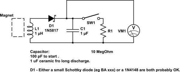
DIY kinetic energy harvester
A DIY kinetic energy harvester utilizing the electromagnetic method to generate electricity. The materials that will be used are currently known.
The project involves creating a kinetic energy harvester that converts mechanical energy from motion into electrical energy through electromagnetic induction....
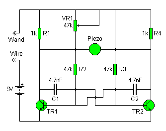
wonky wire
The Wonky Wire circuit is based on the same oscillator used for the Flashing LED Lights. The timing components (R1/C1 and R4/C2) are significantly smaller, resulting in a higher oscillation frequency of approximately 3 kHz (3000 cycles per second). A...

how to convert a 9v battery to 3.7v
A regulator circuit is needed for this DIY project. Familiarity with electronic components, circuitry, the use of a multitester, and a soldering iron is essential. The schematic diagram provided can accept an input voltage ranging from 6 to 24 volts...
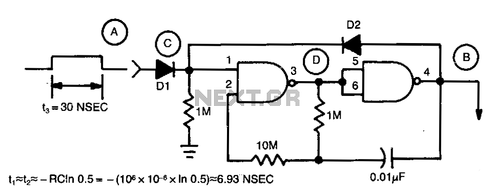
Last-cycle-completing-gated-oscillator
Regenerative feedback at capacitor C allows the oscillator to complete its timing cycle instead of shutting off immediately. The integrated circuit (IC) used was a CD4011AE, although an equivalent IC will also function.
The described circuit utilizes regenerative feedback to enhance...

Electronic Organ Circuit
This electronic organ circuit is straightforward to construct and primarily consists of an emitter-coupled oscillator formed by transistors T2 and T3. A square wave voltage can be obtained from the collector of T3 (X2), which imparts a clarinet-like quality to...