


Metal Detector Cirduit with IC TDA0161
#TDA0161
#oscillator
#Eddy current
#metallic detection
#high frequency
#sensor
#current variation
#proximity detection

Description: The metal detector project is designed for detecting metallic objects by sensing variations in high-frequency eddy current losses. It employs an externally-tuned circuit that functions as oscillators. The output signal level is modified by the presence of an approaching metallic object, which influences the supply current. This current is either high or low, depending on the proximity of a metallic object located between pins 3 and 7 of the integrated circuit, which behaves like a negative resistor equivalent to the external resistor R3 and the trimmer potentiometer PR1 connected between pins 2 and 4. Oscillation ceases when the loss resistance of the tuned circuit (Rp) falls below R3, resulting in a supply current of ICC(close) = 10mA at pins 1 and 6. Conversely, oscillation continues when Rp exceeds R3, yielding a supply current of ICC(remote) = 1mA at pins 1 and 6. The value of Rp is determined by the eddy currents induced by coil L1 in a metallic object.
The metal detector circuit operates on the principle of eddy current induction, where a coil (L1) generates a magnetic field that induces currents in nearby metallic objects. As a metallic object approaches, the eddy currents generated within it lead to variations in the magnetic field, which in turn influences the oscillation characteristics of the circuit. The circuit is designed with an integrated circuit (IC) that includes a feedback mechanism to stabilize the oscillation frequency based on the detected eddy current losses.
The circuit's performance is heavily reliant on the tuning of the external components, specifically the resistor R3 and the trimmer potentiometer PR1. These components allow for precise adjustments to the circuit's threshold sensitivity, enabling the detection of metallic objects at varying distances. The negative resistance behavior of the IC between pins 3 and 7 is crucial for maintaining oscillation, as it counteracts losses in the tuned circuit.
When a metallic object is detected, the loss resistance Rp decreases, leading to a higher supply current (ICC(close)). This change can be monitored and utilized to trigger an alert or activate additional circuitry, such as an indicator light or a sound alarm. Conversely, when the metallic object is removed, the supply current drops (ICC(remote)), indicating the absence of a metallic presence.
The design of the metal detector circuit is robust, allowing for operation independent of supply voltage variations, provided that the voltage remains within specified limits. This feature enhances the circuit's versatility for various applications, including security, treasure hunting, and industrial metal detection. The careful selection of components and the tuning of the circuit parameters ensure reliable performance across different environmental conditions and object types.The Metal detector project is designed for metallic body detection by sensing variations in high frequency Eddy current losses. Using an externally-tuned circuit, they act as oscillators. The output signal level is altered by an approaching metallic object. The output signal is determined by supply current changes. Independent of supply voltage, this current is high or low, according to the presence or absence of a closely located metallic object Between pins 3 and 7, the integrated circuit acts like a negative resistor with a value equal to that of the external resistor R3 and trimmer potentiometer PR1 (connected between pins 2 and 4). The oscillation stops when the tuned circuit loss resistance (Rp) becomes smaller than R3. As a result, ICC(close) = 10mA (pins 1 and 6). The oscillation is sustained when Rp is higher than R3, and ICC(remote) = 1mA (pins 1 and 6). Eddy currents induced by coil L1 in a metallic body determine the value of Rp.
The metal detector circuit operates on the principle of eddy current induction, where a coil (L1) generates a magnetic field that induces currents in nearby metallic objects. As a metallic object approaches, the eddy currents generated within it lead to variations in the magnetic field, which in turn influences the oscillation characteristics of the circuit. The circuit is designed with an integrated circuit (IC) that includes a feedback mechanism to stabilize the oscillation frequency based on the detected eddy current losses.
The circuit's performance is heavily reliant on the tuning of the external components, specifically the resistor R3 and the trimmer potentiometer PR1. These components allow for precise adjustments to the circuit's threshold sensitivity, enabling the detection of metallic objects at varying distances. The negative resistance behavior of the IC between pins 3 and 7 is crucial for maintaining oscillation, as it counteracts losses in the tuned circuit.
When a metallic object is detected, the loss resistance Rp decreases, leading to a higher supply current (ICC(close)). This change can be monitored and utilized to trigger an alert or activate additional circuitry, such as an indicator light or a sound alarm. Conversely, when the metallic object is removed, the supply current drops (ICC(remote)), indicating the absence of a metallic presence.
The design of the metal detector circuit is robust, allowing for operation independent of supply voltage variations, provided that the voltage remains within specified limits. This feature enhances the circuit's versatility for various applications, including security, treasure hunting, and industrial metal detection. The careful selection of components and the tuning of the circuit parameters ensure reliable performance across different environmental conditions and object types.The Metal detector project is designed for metallic body detection by sensing variations in high frequency Eddy current losses. Using an externally-tuned circuit, they act as oscillators. The output signal level is altered by an approaching metallic object. The output signal is determined by supply current changes. Independent of supply voltage, this current is high or low, according to the presence or absence of a closely located metallic object Between pins 3 and 7, the integrated circuit acts like a negative resistor with a value equal to that of the external resistor R3 and trimmer potentiometer PR1 (connected between pins 2 and 4). The oscillation stops when the tuned circuit loss resistance (Rp) becomes smaller than R3. As a result, ICC(close) = 10mA (pins 1 and 6). The oscillation is sustained when Rp is higher than R3, and ICC(remote) = 1mA (pins 1 and 6). Eddy currents induced by coil L1 in a metallic body determine the value of Rp.

Simple triangle-square wave oscillator
By making Rt variable, it is possible to alter the operating frequency over a 100 to 1 range. The versatile triangle/square wave oscillator has a possible frequency range of 0 Hz to 100 kHz.
The described circuit features a variable resistor,...

Metal detector 4
The metal detector circuit comprises a detection oscillator, a reference oscillator, a mixer, and a signal display, as illustrated in Figure 8-70. The detection oscillator circuit is made up of the time base oscillator IC1, inductor L1, potentiometer RP1, diode...

Gate automatic lamp circuit
The circuit utilizes multiple integrated circuits to form an automatic lighting device that is activated by door and window sensors. It includes CD4093 digital integrated circuits, a relay, and a power supply circuit. The system typically remains closed when a...

Metal detector circuit diagram 6
The metal detector circuit consists of several key components including the probe oscillator, reference oscillator, oscillation signal processor, mixing amplifier, and ammeter PA. The probe oscillator is made up of the oscillating tube VI, exploration coil L1, capacitors C1 to...

Minimal metal detector
This circuit is an oscillator with LI being a 4-inch diameter coil consisting of 35 turns of #26 magnet wire. Metal in proximity to LI will cause the oscillator to shift frequency. An AM transistor radio is used to detect...

Metallic pipe detector
This circuit employs a 15-kHz oscillator coil. When metal is removed from the energy field, the oscillator voltage is rectified and compared to a reference. A decrease in oscillator voltage activates comparator IC2, causing D4 (LED) to turn off.
L1 consists...

Metal detector circuit diagram 8
The metal detector circuit consists of a probe oscillator, a PLL (phase-locked loop) circuit, and an audio alarm circuit. The probe oscillator includes a detection coil (L), transistor (V1), and several resistors (R1 to R3) and capacitors (C1 to C5)....
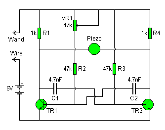
wonky wire
The Wonky Wire circuit is based on the same oscillator used for the Flashing LED Lights. The timing components (R1/C1 and R4/C2) are significantly smaller, resulting in a higher oscillation frequency of approximately 3 kHz (3000 cycles per second). A...

Oscillator DesignGuide Reference
The Oscillator Design Guide is integrated into Agilent EEsof's Advanced Design System environment, functioning as a smart library and interactive handbook for the creation of effective designs. It facilitates quick oscillator design, interactive component characterization, and provides in-depth insights into...