


metal detector using beat frequency
#CMOS 4011
#LM7805L
#9V battery
#beat frequency
#low power
#battery-operated
#voltage regulator
#NAND gates
#metal detection

Description: The NAND gates utilize a CMOS 4011 chip, which is a low-power component ideal for battery-operated circuits. This chip is powered by a 5V voltage supplied from an LM7805L regulator. The purpose of this regulation is to maintain a constant voltage source for the reference oscillator's frequency stability, as the frequency can be influenced by variations in the power supply voltage, particularly as the voltage of the 9V battery decreases over prolonged use.
The CMOS 4011 chip is a quad 2-input NAND gate that offers significant advantages in low-power applications, making it suitable for battery-operated devices. The LM7805L is a linear voltage regulator that provides a stable output voltage of 5V, which is essential for ensuring the reliable operation of the NAND gates. As the battery discharges over time, its voltage can fluctuate, which may lead to instability in the oscillator frequency if the power supply is not regulated.
The LM7805L regulator operates by accepting a higher input voltage—in this case, the 9V from the battery—and outputting a regulated 5V. It features built-in overcurrent and thermal protection, which enhances the reliability of the circuit. The input and output capacitors are recommended to stabilize the voltage and improve transient response. Typically, a 0.33µF capacitor is placed at the input, while a 0.1µF capacitor is placed at the output of the LM7805L to filter out noise and ensure smooth operation.
In summary, the combination of the CMOS 4011 NAND gates and the LM7805L voltage regulator creates a robust and efficient circuit that operates effectively in battery-powered applications. The regulated 5V supply ensures that the NAND gates function optimally, maintaining oscillator frequency stability despite the gradual decline in battery voltage. This design consideration is crucial for applications requiring consistent performance over extended periods.The NAND gates use CMOS 4011 chip, a low power component that is suitable for this battery-operated circuit. You can see that this chip is supplied by a 5V voltage coming from an LM7805L regulator. You might wonder what the purpose of this regulation is, since the power supply come from a 9V battery and the CMOS gates can handle the voltage of 3-1
5 Volt. The main purpose of the regulator is to keep a constant voltage source for the reference oscillator frequency stability, since the frequency is affected by the power supply voltage variation as the battery voltage drops in the long time of usage.
The CMOS 4011 chip is a quad 2-input NAND gate that offers significant advantages in low-power applications, making it suitable for battery-operated devices. The LM7805L is a linear voltage regulator that provides a stable output voltage of 5V, which is essential for ensuring the reliable operation of the NAND gates. As the battery discharges over time, its voltage can fluctuate, which may lead to instability in the oscillator frequency if the power supply is not regulated.
The LM7805L regulator operates by accepting a higher input voltage—in this case, the 9V from the battery—and outputting a regulated 5V. It features built-in overcurrent and thermal protection, which enhances the reliability of the circuit. The input and output capacitors are recommended to stabilize the voltage and improve transient response. Typically, a 0.33µF capacitor is placed at the input, while a 0.1µF capacitor is placed at the output of the LM7805L to filter out noise and ensure smooth operation.
In summary, the combination of the CMOS 4011 NAND gates and the LM7805L voltage regulator creates a robust and efficient circuit that operates effectively in battery-powered applications. The regulated 5V supply ensures that the NAND gates function optimally, maintaining oscillator frequency stability despite the gradual decline in battery voltage. This design consideration is crucial for applications requiring consistent performance over extended periods.The NAND gates use CMOS 4011 chip, a low power component that is suitable for this battery-operated circuit. You can see that this chip is supplied by a 5V voltage coming from an LM7805L regulator. You might wonder what the purpose of this regulation is, since the power supply come from a 9V battery and the CMOS gates can handle the voltage of 3-1
5 Volt. The main purpose of the regulator is to keep a constant voltage source for the reference oscillator frequency stability, since the frequency is affected by the power supply voltage variation as the battery voltage drops in the long time of usage.

Mobile voltage regulator
This simple mobile voltage regulator circuit may save your two-meter or CB transceiver if the voltage regulator fails. The 2N3055 should be heat-sinked if the current drawn by the rig exceeds 2 A during transmission. This circuit will do little...

avr case
Bruco Integrated Circuits B.V. - Case: Automotive alternator voltage regulator - Bruco.
The automotive alternator voltage regulator designed by Bruco Integrated Circuits B.V. is a critical component in modern vehicle electrical systems. This device is responsible for regulating the voltage output...

DC Power Supply 9 volt using TIP31 transistor
This is a DC power supply circuit designed to regulate 9 volts and provide a current output ranging from 1 amp to 2 amps. The circuit utilizes a modified TIP31 transistor, although alternative transistors such as TIP41, MJE3055, or 2SC1061...

A TREAD sized regulator
The size of the tread was 5 cm by 3 cm. The current design measures 5 cm by 3.3 cm. The regulator's foundation is based on Walt Jung's 1997 article, "Regulator Excels in Noise and Line Rejection," with modifications derived...

Universal Laboratory Power Supply Circuit
The design's value is derived from the use of IC1, an LM317HVK adjustable series-pass voltage regulator, which provides broad-range performance along with voltage-setting and current-limiting functions. The input to IC1 is sourced from the output of BR1, which is filtered...
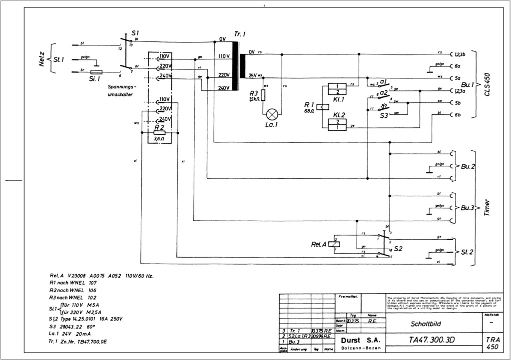
Durst power supplies EST 301 and EST 450
The regulator board of the ES301 has been inspected, revealing that the PCB contacts of the current sensing resistors R42 and R43 are severely burned. There is a nearby group of resistors that also need to be replaced, but their...

Application Circuit CW4960 CW4962 dual voltage + 5V 1.5A -12V 100mA output
The circuit described is a stabilized power supply utilizing the CW4962 and CW4960 components, providing +5V at 1.5A and -12V at 100mA. The +5V output serves as the main power supply. The output circuit employs a transformer rather than an...

Multifunction appliance protection circuit diagram
The circuit consists of a DC voltage regulator, a delay circuit, and protection mechanisms for overvoltage and undervoltage. It utilizes the LM7812 integrated voltage regulator to provide a stable 12V output. The protection circuit samples voltage using R2 and potentiometer...

Multipurpose Flip-Flop Timer
This timing circuit is designed to time one-shot events ranging from a few seconds to several hours. In standby mode, with RLY1 and LED1 turned off, the power consumption is minimal. The main component of this circuit is a low-cost...