


TDA0161 Metal Detector
#TDA0161
#LED indicator
#sensitivity adjustment
#manual reset
#hysteresis
#metal detection
#schematic
#electronic design
#sensor
#DIY

Description: This circuit features an LED indicator with two identical LEDs depicted in the schematic. The modification in Advanced Schematic-2 enhances the detector's sensitivity by incorporating a manual reset function to eliminate the built-in hysteresis of the integrated circuit (IC). Standard trimpots are utilized for the 10K and 1K adjustments. It is noted that alternative coil values can be employed, provided that the corresponding trimpot and "CX" capacitor values are adjusted accordingly. The following steps outline the setup: 1) Ensure that no metal is near the coil. 2) Set the fine adjustment to a mid-position. 3) Adjust the coarse adjustment until the LED just turns on. 4) Subsequently, adjust the fine adjustment until the LED turns off. 5) Carefully adjust the fine control to turn the LED back on and take note of this position. 6) Slightly back off this setting. Activating the manual reset should turn off the LED, and introducing metal near the coil will reactivate it. Pressing the manual reset again will turn it off for subsequent metal detection.
This circuit is designed to operate as a metal detector, utilizing two identical LEDs as indicators for detection status. The inclusion of a manual reset mechanism is a significant enhancement, allowing the user to reset the detection state without the interference of built-in hysteresis present in many integrated circuits. The use of standard trimpots for fine-tuning the sensitivity is crucial, with specific values of 10K and 1K recommended for optimal performance.
The circuit's operation can be summarized in a series of calibration steps that ensure effective detection. Initially, it is essential to eliminate any metallic interference near the coil to prevent false triggering. The calibration process begins by setting the fine adjustment to a midpoint, providing a baseline for sensitivity adjustments. The coarse adjustment is then employed to bring the LED to its activation threshold, indicating the circuit's readiness to detect metal.
Once the LED is activated, the fine adjustment is used to fine-tune the sensitivity to the point where the LED turns off, indicating that the circuit is not detecting any metal. It is critical to carefully adjust the fine control to the point where the LED just turns back on, as this setting represents the threshold for sensitivity. Recording this position allows for precise adjustments in future calibrations.
After noting this adjustment, a slight reduction in the setting ensures that the LED can be turned off with the manual reset, allowing for a clear indication of metal detection when the coil is activated by the presence of metal. The manual reset feature is particularly useful for conducting multiple searches without the need to recalibrate the circuit each time. By following these steps, the circuit can effectively detect metal objects in its vicinity, providing reliable performance in various applications.This particular circuit was built with an LED Indicator. There are Two LED`s Shown in the Schematic, Both do Exactly the same thing. I was just Playing with it. Advanced Schematic-2 This Modification in Advance Schematic-2 "Will Make this detector More Sensitive", by using a "Manual Reset" to help eliminate the IC`s, "Built in Hysteresis". Use Sta ndard Trimpot for the 10K and 1K Adjustments. Note: Other Coil values can Also be used, if you also use the Appropriate Values for the Trimpots and "CX" Capacitors. These are the values I used. 1) Make Sure there is NO METAL Near the Coil. 2) Set the Fine Adjustment to a "Mid Position". 3) Adjust the Course Adjustment to "Just Turn on the LED" 4) Than adjust the Fine Adjustment to Turn OFF the LED.
5) Now "Very Carefully" adjust the fine adjust to "JUST TURN the LED Back ON" and take "Careful Note of this Setting Position". 6) Now Just Back off this Setting a "TINY BIT". Pushing the "Manual Reset" Should now Turn Off the LED. Than Placing metal towards the coil will turn it back on. Pushing the Manual Reset, again turns it Off for doing another search for metal.
This circuit is designed to operate as a metal detector, utilizing two identical LEDs as indicators for detection status. The inclusion of a manual reset mechanism is a significant enhancement, allowing the user to reset the detection state without the interference of built-in hysteresis present in many integrated circuits. The use of standard trimpots for fine-tuning the sensitivity is crucial, with specific values of 10K and 1K recommended for optimal performance.
The circuit's operation can be summarized in a series of calibration steps that ensure effective detection. Initially, it is essential to eliminate any metallic interference near the coil to prevent false triggering. The calibration process begins by setting the fine adjustment to a midpoint, providing a baseline for sensitivity adjustments. The coarse adjustment is then employed to bring the LED to its activation threshold, indicating the circuit's readiness to detect metal.
Once the LED is activated, the fine adjustment is used to fine-tune the sensitivity to the point where the LED turns off, indicating that the circuit is not detecting any metal. It is critical to carefully adjust the fine control to the point where the LED just turns back on, as this setting represents the threshold for sensitivity. Recording this position allows for precise adjustments in future calibrations.
After noting this adjustment, a slight reduction in the setting ensures that the LED can be turned off with the manual reset, allowing for a clear indication of metal detection when the coil is activated by the presence of metal. The manual reset feature is particularly useful for conducting multiple searches without the need to recalibrate the circuit each time. By following these steps, the circuit can effectively detect metal objects in its vicinity, providing reliable performance in various applications.This particular circuit was built with an LED Indicator. There are Two LED`s Shown in the Schematic, Both do Exactly the same thing. I was just Playing with it. Advanced Schematic-2 This Modification in Advance Schematic-2 "Will Make this detector More Sensitive", by using a "Manual Reset" to help eliminate the IC`s, "Built in Hysteresis". Use Sta ndard Trimpot for the 10K and 1K Adjustments. Note: Other Coil values can Also be used, if you also use the Appropriate Values for the Trimpots and "CX" Capacitors. These are the values I used. 1) Make Sure there is NO METAL Near the Coil. 2) Set the Fine Adjustment to a "Mid Position". 3) Adjust the Course Adjustment to "Just Turn on the LED" 4) Than adjust the Fine Adjustment to Turn OFF the LED.
5) Now "Very Carefully" adjust the fine adjust to "JUST TURN the LED Back ON" and take "Careful Note of this Setting Position". 6) Now Just Back off this Setting a "TINY BIT". Pushing the "Manual Reset" Should now Turn Off the LED. Than Placing metal towards the coil will turn it back on. Pushing the Manual Reset, again turns it Off for doing another search for metal.

Automatic Room light Control With Bi Directional Visitor Counter
The objective of this project is to create a controller-based model that counts the number of individuals entering a specific room and activates the lighting accordingly. This is achieved through the use of sensors that detect the current number of...

Gate automatic lamp circuit
The circuit utilizes multiple integrated circuits to form an automatic lighting device that is activated by door and window sensors. It includes CD4093 digital integrated circuits, a relay, and a power supply circuit. The system typically remains closed when a...
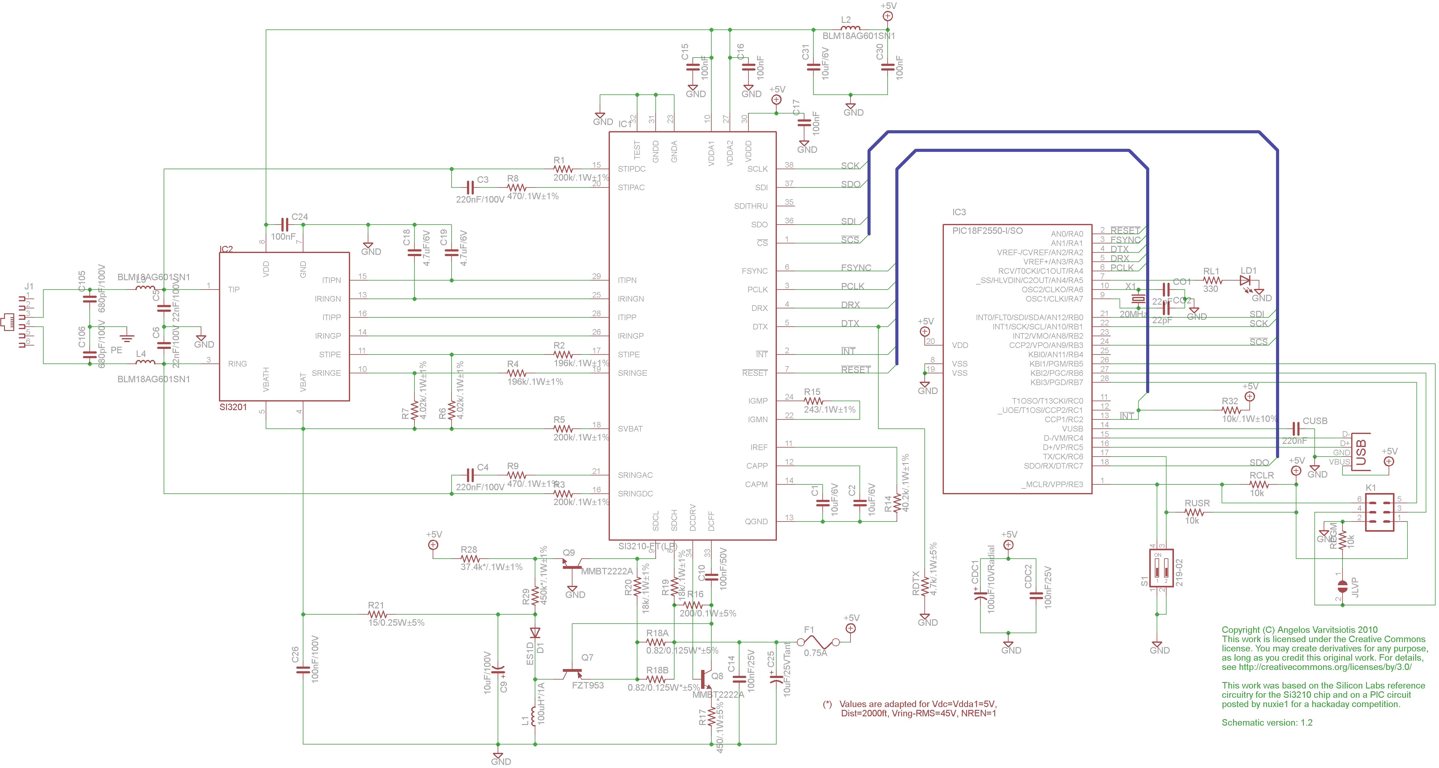
dyi setup and debugging guide
This page discusses the differences between assembled Open USB FXS dongle boards and DIY boards. While the assembled boards are fully tested and quality control approved, DIY boards may encounter various issues during assembly. Fortunately, most of these issues can...
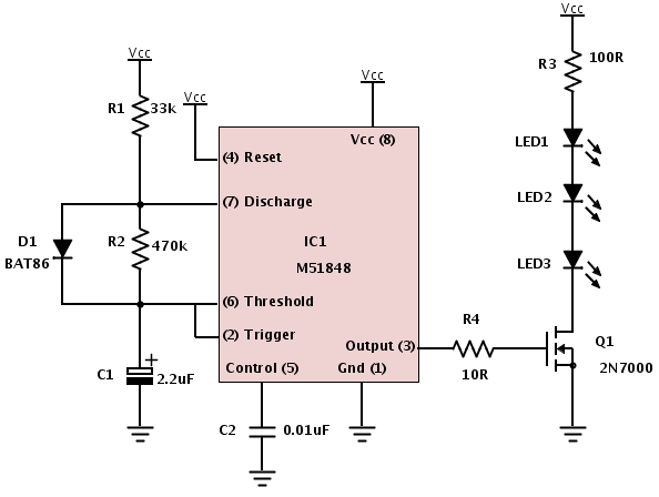
Building a device from a schematic
A common issue encountered is that individuals possess a schematic, also known as a circuit diagram, that they wish to construct. However, they discover that there are...
Building a circuit from a schematic requires a clear understanding of the components involved...
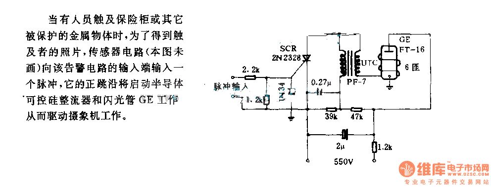
The alarm circuit diagram for safety box and other metal objects
When an individual touches the safety box or other protected metal objects, the sensor circuit generates a pulse to the alarm circuit. The positive edge of this pulse activates the semiconductor and thyristor flash GE, subsequently triggering the camera to...

How to Read a Schematic
Electronic circuits are presented in schematic form. A schematic is essentially a map that illustrates the path of current through various components. Each component is represented by a symbol, typically accompanied by a label or a value, or both. The...

5 Minute Signal
For the past year and a half, a group based in Ann Arbor, Michigan, named GO-Tech has been formed, uniting individuals interested in creating projects using technology, such as hardware, software, metal, and wood. This initiative is referred to as...
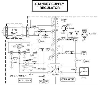
Need to have the circuit schematic for LG 29SA1RL model
The schematic is in PDF format and cannot be sent through this site. It is recommended to check a specific website that contains various schematics, including older posts that might have the schematic needed. A WS-55807 model is experiencing issues...

Field disturbance sensor-alarm
The change in ambient light triggers the alarm by changing the resistance of LDR1 and LDR2.
The circuit utilizes two light-dependent resistors (LDR1 and LDR2) to detect variations in ambient light levels. LDRs are passive components that exhibit a change in...