


TDA0161 metal detector electronic schematic
#TDA0161
#Eddy current
#high frequency
#metallic body detection
#supply current
#monolithic integrated circuit
#schematic
#electronic circuit
#detection circuit
#sensor

Description: This metal detector circuit diagram utilizes the TDA0161 monolithic integrated circuit, which is designed to detect metallic objects by measuring variations in high-frequency Eddy current losses. The output signal is influenced by changes in supply current, which varies based on the presence or absence of a nearby metallic object, independent of the supply voltage. The circuit employs two LEDs to provide a visual indication of the presence or absence of metals around the coil. To calibrate the circuit, it is essential to ensure that there are no metallic objects near the coil. The fine adjustment should be set to a mid-position, followed by adjusting the coarse setting to activate the LED, and then fine-tuning to deactivate the LED.
The TDA0161 integrated circuit is central to the operation of this metal detector. It operates by generating a high-frequency signal that induces Eddy currents in nearby metallic objects. As these currents circulate, they produce their own magnetic fields, which the circuit detects as variations in the original signal. The sensitivity of the circuit can be adjusted to accommodate different types of metals and their distances from the coil.
The circuit design includes a power supply that stabilizes the voltage, ensuring consistent performance regardless of fluctuations in input power. The two LEDs serve as indicators: one LED lights up when metal is detected, while the other may indicate a lack of detection. This dual-indicator system allows for easy interpretation of the circuit's status.
Calibration of the metal detector is crucial for optimal performance. The initial step involves ensuring that the vicinity of the coil is free from metallic interference. Setting the fine adjustment to the mid-position provides a baseline for further adjustments. The coarse adjustment is then used to activate the LED, indicating that the circuit is responsive to metal detection. Finally, the fine adjustment is utilized to turn off the LED, confirming that the circuit is correctly calibrated to ignore background noise and only respond to significant metallic objects.
Overall, this metal detector circuit is a practical application of the TDA0161 IC, demonstrating effective detection capabilities through a straightforward calibration process and visual feedback via LED indicators.This metal detector circuit diagram is based on the TDA0161 monolithic integrated circuit, designed for metallic body detection by detecting the variations in high frequency Eddy current losses. Output signal is determined by supply current changes. Independent of supply voltage, this current is high or low according to the presence or the absenc e of a close metallic object. Using two LEDs this circuit provide an visual indication of presence or absence at a metals around the coil. To adjust the circuit you need to make sure there is no metal near the coil and then set the fine adjustment to a "Mid position".
After that you need to adjust the course adjustment to turn on the LED and, adjust the fine adjustment to turn off the LED.
The TDA0161 integrated circuit is central to the operation of this metal detector. It operates by generating a high-frequency signal that induces Eddy currents in nearby metallic objects. As these currents circulate, they produce their own magnetic fields, which the circuit detects as variations in the original signal. The sensitivity of the circuit can be adjusted to accommodate different types of metals and their distances from the coil.
The circuit design includes a power supply that stabilizes the voltage, ensuring consistent performance regardless of fluctuations in input power. The two LEDs serve as indicators: one LED lights up when metal is detected, while the other may indicate a lack of detection. This dual-indicator system allows for easy interpretation of the circuit's status.
Calibration of the metal detector is crucial for optimal performance. The initial step involves ensuring that the vicinity of the coil is free from metallic interference. Setting the fine adjustment to the mid-position provides a baseline for further adjustments. The coarse adjustment is then used to activate the LED, indicating that the circuit is responsive to metal detection. Finally, the fine adjustment is utilized to turn off the LED, confirming that the circuit is correctly calibrated to ignore background noise and only respond to significant metallic objects.
Overall, this metal detector circuit is a practical application of the TDA0161 IC, demonstrating effective detection capabilities through a straightforward calibration process and visual feedback via LED indicators.This metal detector circuit diagram is based on the TDA0161 monolithic integrated circuit, designed for metallic body detection by detecting the variations in high frequency Eddy current losses. Output signal is determined by supply current changes. Independent of supply voltage, this current is high or low according to the presence or the absenc e of a close metallic object. Using two LEDs this circuit provide an visual indication of presence or absence at a metals around the coil. To adjust the circuit you need to make sure there is no metal near the coil and then set the fine adjustment to a "Mid position".
After that you need to adjust the course adjustment to turn on the LED and, adjust the fine adjustment to turn off the LED.

7MHz high frequency carrier oscillator
The 2SA130 transistor is used in an oscillator circuit with an oscillation frequency of 7 MHz. The power supply voltage is 6V, and the load is a frequency-selective resonant circuit with a quality factor of 600.
The circuit utilizes the 2SA130...
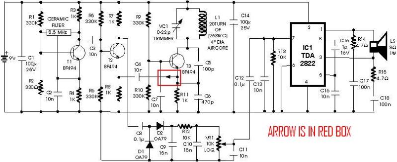
metal detector project circuit
A schematic diagram for a metal detector has been found. The project does not need to be original and can be sourced from the internet. There are several questions regarding this schematic. One query pertains to a small arrow connected...

Varactorless high frequency modulator circuit design electronic project
This varactorless high-frequency modulator electronic project must be powered by a simple DC 3-volt power source, such as a 3-volt battery. Traditionally, high-frequency oscillators are frequency-modulated using a varactor. However, varactors typically require a significant voltage change to achieve an...
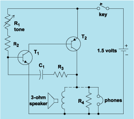
schematic diagram graphic arts
Schematic diagram. A presentation of the element-by-element relationship of all parts of a system.
A schematic diagram serves as a crucial tool in electronic design and engineering, representing the interconnections and relationships between various components within a system. It provides a...

Add a sensor to a board and measure something with it
This week's plan is to build a device that warns of the potential for a knockdown, which is the process by which an over-canvassed ship is laid over on her beam-ends. The risk of sinking is high during this event,...

Automatic Room light Control With Bi Directional Visitor Counter
The objective of this project is to create a controller-based model that counts the number of individuals entering a specific room and activates the lighting accordingly. This is achieved through the use of sensors that detect the current number of...

Pots water alarm circuit
The flowers in pots require watering, as relying solely on the observation of moist soil surfaces can be unreliable. To address this issue, a flower watering indicator has been developed. This circuit includes a field effect transistor (VT1), a second...

Automatic plant waterer
The unit consists of a sensor, timer, and electric water pump. The sensor is embedded in the soil, and when dry, the electronics operate the water pump for a preset time. The circuit is composed of a level-sensitive Schmitt trigger,...
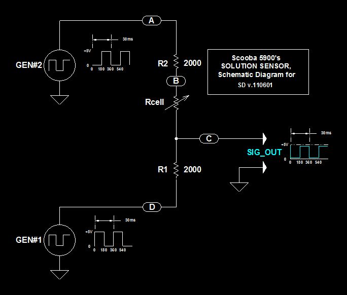
Scoobas Solution Sensing Tactic
This document serves multiple purposes, primarily to document the methods employed by a Scooba robot to detect: a) the presence of an acceptable cleaning solution being delivered to its pump, and b) the excess presence of used solution collected off...