


5-channel low-power interface circuit programmable sensor signal processor AD7714 and MCS-51 series microcontroller
#AD7714
#MCS-51
#sensor interface
#low-power
#3-wire serial interface
#programmable
#signal processor
#microcontroller

Description: The 3-wire interface to the AD7714 can be utilized with various microcontrollers, including microcontrollers and microprocessors. This 3-wire serial interface is particularly suitable for isolation systems, allowing the use of optical couplers. The interface circuit between the AD7714 and the 80C51 (or 87C51, 89C51, etc.) microcontroller is illustrated in a referenced figure. The 80C51 microcontroller uses only two pins (P3.0 and P3.1) for this connection. In this configuration, the non-DRDY bit in the monitoring configuration register is used to determine when the Data Register is updated. The 80C51 operates in mode 0, which features a single data line in its serial interface, necessitating a short circuit between the DOUT and DIN pins of the AD7714. During data transfer, the serial clock terminal of the 80C51 is set to a high level, while the POL-side fixed contact of the AD7714 remains high.
The AD7714 is a precision analog-to-digital converter (ADC) that communicates via a 3-wire serial interface, making it ideal for applications requiring isolation. This interface allows for the integration of optical couplers, which can enhance system safety by isolating high-voltage sections from sensitive microcontroller components. The 80C51 microcontroller, a widely used device in embedded systems, interfaces with the AD7714 using two of its GPIO pins, specifically P3.0 and P3.1, for data communication.
In this configuration, the microcontroller monitors the non-DRDY (Data Ready) bit in the configuration register to ascertain when new data is available in the ADC's Data Register. This method ensures efficient data handling and minimizes the risk of reading data that has not yet been updated. The use of mode 0 in the 80C51's serial communication simplifies the design by utilizing a single data line, which is critical for reducing the number of required connections and potential points of failure in the circuit.
To facilitate data transfer, the DOUT and DIN pins of the AD7714 are directly connected, allowing for bidirectional communication over the same line. When the 80C51 initiates data transfer, the serial clock (SCLK) is set to a high state, signaling the AD7714 to prepare data for transmission. The fixed high state of the POL-side contact ensures stable operation of the ADC during the communication process. This configuration is particularly advantageous in applications where space and component count must be minimized while maintaining reliable performance.3-wire interface to the AD7714 can be equipped with a variety of microcontrollers (including microcontroller or microprocessor). 3-wire serial interface is particularly suitabl e for the isolation system, allows the system used in the optical coupler in an amount of at least. AD7714 and 80C51 (or 87C51,89C51 etc.) microcontroller interface circuit shown in FIG. Minimum opening line 80C51 used only two (P3.0, P3.1). At this time, by the monitoring configuration register non DRDY bit to determine when the Data Register is updated. 80C51 in mode 0 mode due to its serial interface contains a single data line, so the DOUT and DIN end of the AD7714 should be short-circuited.
When transferring data 80C51 serial clock terminal is set to the high level. POL-side fixed contact AD7714 high.
The AD7714 is a precision analog-to-digital converter (ADC) that communicates via a 3-wire serial interface, making it ideal for applications requiring isolation. This interface allows for the integration of optical couplers, which can enhance system safety by isolating high-voltage sections from sensitive microcontroller components. The 80C51 microcontroller, a widely used device in embedded systems, interfaces with the AD7714 using two of its GPIO pins, specifically P3.0 and P3.1, for data communication.
In this configuration, the microcontroller monitors the non-DRDY (Data Ready) bit in the configuration register to ascertain when new data is available in the ADC's Data Register. This method ensures efficient data handling and minimizes the risk of reading data that has not yet been updated. The use of mode 0 in the 80C51's serial communication simplifies the design by utilizing a single data line, which is critical for reducing the number of required connections and potential points of failure in the circuit.
To facilitate data transfer, the DOUT and DIN pins of the AD7714 are directly connected, allowing for bidirectional communication over the same line. When the 80C51 initiates data transfer, the serial clock (SCLK) is set to a high state, signaling the AD7714 to prepare data for transmission. The fixed high state of the POL-side contact ensures stable operation of the ADC during the communication process. This configuration is particularly advantageous in applications where space and component count must be minimized while maintaining reliable performance.3-wire interface to the AD7714 can be equipped with a variety of microcontrollers (including microcontroller or microprocessor). 3-wire serial interface is particularly suitabl e for the isolation system, allows the system used in the optical coupler in an amount of at least. AD7714 and 80C51 (or 87C51,89C51 etc.) microcontroller interface circuit shown in FIG. Minimum opening line 80C51 used only two (P3.0, P3.1). At this time, by the monitoring configuration register non DRDY bit to determine when the Data Register is updated. 80C51 in mode 0 mode due to its serial interface contains a single data line, so the DOUT and DIN end of the AD7714 should be short-circuited.
When transferring data 80C51 serial clock terminal is set to the high level. POL-side fixed contact AD7714 high.

µP-Controlled Oscillator Delivers Rock-Bottom Distortion
Function generators are essential in the design, testing, and operation of encoders, modulators, demodulators, and measurement instruments. This document presents an economical method to construct a bus-controlled sinewave oscillator that exhibits exceptionally low distortion. The circuit produces a sinusoidal output...

Exploring Microcontrollers
Many of today's appliances feature displays and buttons. Instead of relying on motors and gears, numerous household items now incorporate embedded microcontrollers. This exploration focuses on how to experiment with microcontrollers at home.
Microcontrollers serve as the central processing units for...

Training Boxing timer schematic
A timer is being developed for circuit training or boxing training. The timer does not require any external input, except for a reset function. The project can be simplified using a microcontroller, such as the PIC12F635, which is cost-effective at...

Electronic TIC TAC TOE
This project is not to introduce Tic Tac Toe. Everyone knows this game. It is to introduce two features: bi-coloured LEDs, microcontrollers, and the skill of writing an ALGORITHM. You can use the project to learn the skills of creating...
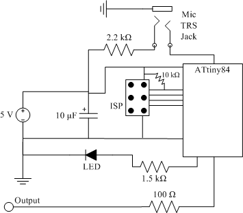
clap sensor construction
The clap sensor is a straightforward circuit that consists of a PC microphone, a microcontroller, and an output. The circuit design features the ATtiny84 microcontroller, chosen for familiarity with the AVR architecture and accessibility to necessary tools. The ATtiny84 is...

Programmable Zener
The ICL8212 is configured as a programmable zener diode, allowing for the programming of zener voltages ranging from 2 V to 30 V by appropriately selecting R2. The zener voltage is influenced by this selection. Additionally, due to the lack...

pc based digital ic tester
Check the following ICs: 7400, 7402, 7404, 7408, 7432, 7486. A Visual Basic program is utilized to display the results on the PC. The microcontroller AT89S52 receives the IC number from the PC, verifies the logic gates with the truth...
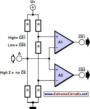
Multitasking Pins circuit
It is entirely logical that low-cost miniature microcontrollers have fewer pins than their larger counterparts, sometimes too few. Consideration has been given to how to economize on pins by making them perform the work of several. It was noted that...

PROGRAMMABLE_TIMER_SEQUENCER
The circuit diagram of this programmable sequencer can be utilized for various timing applications. An audible tone is generated before the start of each interval, while a seven-segment LED display indicates the current interval number. A buzzer sounds again just...