


atmega

Description: After compiling a C or C++ program into an AVR binary using AVR-GCC, the next step is to "burn" the binary onto the chip. This can be accomplished with one of three applications: AVRDUDE, UISP, or AVR Studio. To enable communication between one of these applications and the chip, hardware is required to connect the chip to the computer. The chip features five pins designated for an In-System Programmer (ISP). These pins facilitate the programming of the chip via the computer. A commonly used device for interfacing these ISP pins with a USB port on a PC is the AVRISP mkII, typically priced between $25 and $30, known for its user-friendly operation. Alternatively, a Parallel Port ISP programmer can be constructed, with several designs available, although the simplest version is recommended.
Arduino, an AVR-based prototyping board, emphasizes ease of use and includes breakout headers for input/output pins and power. It also incorporates a USB interface utilizing the FT232RL chip, which enables RS232 serial communication through a USB device, thereby negating the need for a separate AVR programmer. The Arduino project provides an Integrated Development Environment (IDE) for writing AVR code in a C/C++-derived language called Wiring. This IDE includes various libraries and a convenient function framework. The Arduino bootloader will flash Pin 19 (PB5) twice at a 500 ms interval during boot-up, with a low-power LED designated for this purpose or for monitoring the status of custom software. A 470-ohm resistor should be placed in series with the LED.
ATmega chips programmed via the Arduino will function as stand-alone microcontrollers. However, to utilize a new ATmega with the Arduino, it is necessary to write the Arduino bootloader onto the ATmega chip, achievable with AVRDUDE, UISP, or AVR Studio. ATmega chips utilizing the Arduino bootloader will experience a 5-second startup delay during which the bootloader listens for serial data from the Arduino programming environment. If the chip blinks the LED on Pin 13 but does not execute the user code, placing a 10,000-ohm resistor between Pin 2 and Pin 3 is advised, as the bootloader may erroneously interpret noise on these pins as data. Port C connects to the TWI (2-Wire or I²C) module and provides six ADC inputs via the A/D Converter module. It consists of seven I/O pins and supports pin change interrupts. The analog inputs are located on pins PC0 through PC5.
The described system illustrates a typical workflow for programming AVR microcontrollers, emphasizing the integration of hardware and software components. The use of an ISP allows for direct programming of the microcontroller, which is essential for embedded systems development. The Arduino platform serves as a versatile tool for rapid prototyping, enabling users to develop and test applications efficiently. The inclusion of an IDE with libraries enhances the development experience, allowing for easier implementation of complex functionalities. The bootloader mechanism provides a convenient method for uploading new code to the microcontroller without requiring a dedicated programmer after the initial setup. The functionality of Port C, with its ADC capabilities and support for I²C communication, illustrates the versatility of the ATmega chips in handling various input and output tasks, making them suitable for a wide range of applications in embedded systems.Once you have compiled your C or C+ program into an AVR binary using AVR-GCC, you will need to "burn" it to the chip itself. This can be done with one of three applications: AVRDUDE, UISP, or AVR Studio. In order to actually get one of those applications talking to your chip, you will need hardware to plug the chip into your computer.
There are five pins on the chip for something called an In-System Programmer, or ISP for short. These pins are used by your computer to program the chip. A common piece of hardware for connecting these ISP pins to one of your PC`s USB ports is the AVRISP mkII. These usually sell for $25 to $30, and are one of the easiest programmers to use. If you don`t feel like going for one of those, you can also build your own Parallel Port ISP programmer without trouble.
There are a number of designs for a parallel programmer, but this is the simplest. Arduino is an AVR-based prototyping board with an emphasis on ease of use. It has breakout headers for I/O pins and power. It also features a USB interface using the FT232RL chip, which allows RS232 serial communication through a USB device, eliminating the need for a separate AVR programmer. The Arduino project also has an Integrated Development Environment for writing AVR code in a C/C+-derived language called Wiring.
The IDE also includes many helpful libraries and a nice function framework. Check out the Arduino website ! The Arduino bootloader will flash Pin 19 (PB5) twice on a 500ms interval at boot-up. The low-power LED is meant for this, or for your own software`s status monitor. Use the 470 ohm resistor in series with the LED. ATmega chips programmed by the Arduino will work as stand-alone microcontrollers. However, in order to use a new ATmega with the Arduino, you must write the Arduino bootloader to the ATmega chip. This can be done with AVRDUDE, UISP, or AVR Studio. See the "Programming your ATmega Chip" section above. ATmega chips running the Arduino bootloader will have a 5 second delay at startup. This is where the bootloader listens for serial data from the Arduino programming environment. If the chip flashes the LED on Pin 13, but never starts executing your code, then place a 10000 ohm resistor between Pin 2 and Pin 3.
The bootloader may "wait" forever because it mistakes noise for data on those pins. Port C interfaces with the TWI (2-Wire or I ²C) module, and provides 6 ADC inputs by interfacing with the A/D Converter module. Port C has 7 I/O pins, and supports pin change interrupts. Analog inputs are on pins PC0 through PC5
Arduino, an AVR-based prototyping board, emphasizes ease of use and includes breakout headers for input/output pins and power. It also incorporates a USB interface utilizing the FT232RL chip, which enables RS232 serial communication through a USB device, thereby negating the need for a separate AVR programmer. The Arduino project provides an Integrated Development Environment (IDE) for writing AVR code in a C/C++-derived language called Wiring. This IDE includes various libraries and a convenient function framework. The Arduino bootloader will flash Pin 19 (PB5) twice at a 500 ms interval during boot-up, with a low-power LED designated for this purpose or for monitoring the status of custom software. A 470-ohm resistor should be placed in series with the LED.
ATmega chips programmed via the Arduino will function as stand-alone microcontrollers. However, to utilize a new ATmega with the Arduino, it is necessary to write the Arduino bootloader onto the ATmega chip, achievable with AVRDUDE, UISP, or AVR Studio. ATmega chips utilizing the Arduino bootloader will experience a 5-second startup delay during which the bootloader listens for serial data from the Arduino programming environment. If the chip blinks the LED on Pin 13 but does not execute the user code, placing a 10,000-ohm resistor between Pin 2 and Pin 3 is advised, as the bootloader may erroneously interpret noise on these pins as data. Port C connects to the TWI (2-Wire or I²C) module and provides six ADC inputs via the A/D Converter module. It consists of seven I/O pins and supports pin change interrupts. The analog inputs are located on pins PC0 through PC5.
The described system illustrates a typical workflow for programming AVR microcontrollers, emphasizing the integration of hardware and software components. The use of an ISP allows for direct programming of the microcontroller, which is essential for embedded systems development. The Arduino platform serves as a versatile tool for rapid prototyping, enabling users to develop and test applications efficiently. The inclusion of an IDE with libraries enhances the development experience, allowing for easier implementation of complex functionalities. The bootloader mechanism provides a convenient method for uploading new code to the microcontroller without requiring a dedicated programmer after the initial setup. The functionality of Port C, with its ADC capabilities and support for I²C communication, illustrates the versatility of the ATmega chips in handling various input and output tasks, making them suitable for a wide range of applications in embedded systems.Once you have compiled your C or C+ program into an AVR binary using AVR-GCC, you will need to "burn" it to the chip itself. This can be done with one of three applications: AVRDUDE, UISP, or AVR Studio. In order to actually get one of those applications talking to your chip, you will need hardware to plug the chip into your computer.
There are five pins on the chip for something called an In-System Programmer, or ISP for short. These pins are used by your computer to program the chip. A common piece of hardware for connecting these ISP pins to one of your PC`s USB ports is the AVRISP mkII. These usually sell for $25 to $30, and are one of the easiest programmers to use. If you don`t feel like going for one of those, you can also build your own Parallel Port ISP programmer without trouble.
There are a number of designs for a parallel programmer, but this is the simplest. Arduino is an AVR-based prototyping board with an emphasis on ease of use. It has breakout headers for I/O pins and power. It also features a USB interface using the FT232RL chip, which allows RS232 serial communication through a USB device, eliminating the need for a separate AVR programmer. The Arduino project also has an Integrated Development Environment for writing AVR code in a C/C+-derived language called Wiring.
The IDE also includes many helpful libraries and a nice function framework. Check out the Arduino website ! The Arduino bootloader will flash Pin 19 (PB5) twice on a 500ms interval at boot-up. The low-power LED is meant for this, or for your own software`s status monitor. Use the 470 ohm resistor in series with the LED. ATmega chips programmed by the Arduino will work as stand-alone microcontrollers. However, in order to use a new ATmega with the Arduino, you must write the Arduino bootloader to the ATmega chip. This can be done with AVRDUDE, UISP, or AVR Studio. See the "Programming your ATmega Chip" section above. ATmega chips running the Arduino bootloader will have a 5 second delay at startup. This is where the bootloader listens for serial data from the Arduino programming environment. If the chip flashes the LED on Pin 13, but never starts executing your code, then place a 10000 ohm resistor between Pin 2 and Pin 3.
The bootloader may "wait" forever because it mistakes noise for data on those pins. Port C interfaces with the TWI (2-Wire or I ²C) module, and provides 6 ADC inputs by interfacing with the A/D Converter module. Port C has 7 I/O pins, and supports pin change interrupts. Analog inputs are on pins PC0 through PC5

Hum Circuit
The kit employs an off-the-shelf microcontroller based on the AtMega328P-PU Arduino, along with a simplified version designed for ease of replication and modification by collaborators and students. This initiative aims to enable the fabrication of simplified microcontrollers for DIY synthetic...

MICROCONTROLLER BASED AUTOMATIC ROOM LIGHT CONTROLLER
This project involves an automatic room light controller with a bidirectional visitor counter using a microcontroller. It is designed to manage room lighting and accurately count the number of individuals present. When a person enters the room, the counter increments...

AVR LCD Microcontrolled Oscilloscope
A few months ago as I was surfing on the net, I saw an oscilloscope based on PIC18F2550 microcontroller and a KS0108 controller based graphical LCD. That was Steven Cholewiak's web site. I had never seen before so amazing microcontroller-only...

AVR/Arduino ISP programmer using the Raspberry Pi GPIOs
As a fully-featured Linux computer, many external programmers can be used with the Raspberry Pi to program the Atmel AVR range of microprocessors. It is also possible to utilize the general-purpose input/output lines (GPIOs) found on the Raspberry Pi to...

avr parallel programmer 5
The primary advantage of this programmer is its capability to safeguard both the target device and the PC from unexpected voltages when either side is powered down. The buffers utilized are open-drain, with each buffer connected to the Vcc of...

Flashflex Microcontroller Control Of Character Lcd Module
The FM497 is an integrated electronic ignition controller designed for breakerless ignition systems that utilize Hall effect sensors. This device operates an external NPN Darlington transistor to manage the coil current, thereby delivering the necessary stored energy while maintaining low...

Ponyprog Circuit for ATMEL AVRs
The schematic includes programmable AVRs. For other members of the AVR family or additional programmable ICs compatible with Ponyprog, there is a J1 connector (CON10) that facilitates hardware expansion of the programmer. Additional information about compatible ICs can be found...
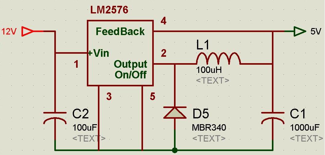
Some Voltage Regulator Ciruits for Microcontroller based Projects
A regulated and noise-free power supply voltage is essential for microcontrollers and other components such as amplifiers, filters, and GPS devices. Voltage surges in the supply voltage can permanently damage embedded systems. A voltage regulator must maintain the output voltage...

Miniature Real-time Controller
This is my long history the device that controls my home's night light, air-conditioner, etc. The device is a Miniature Real-time Controller. The circuit uses only three chips, a 89C2051, DS275 (or MAX232), and 74LS07 open collector driver. The scheduler...