


ATMEL 89 Series Flash Microcontroller
#AT89
#flash microcontroller
#programmer
#parallel port
#TTL
#PC interface
#hardware
#electronics
#DIY

Description: This programmer was designed to be flexible, economical, and easy to build. The programmer hardware utilizes standard TTL series parts, and no special components are used. The programmer is interfaced with the PC parallel port, and there are no special requirements for the PC parallel port, so older computers can also be used with this programmer. The programmer software supports the following Atmel devices: AT89C51, AT89C1051, AT89C52, AT89C1051U, AT89C55, AT89C2051, AT89S53, AT89C4051, AT89S8252, and AT89C55WD. Note: For 20 pin devices, a simple interface adapter is required. The AT89C55WD has been included for testing purposes. Figure 1 shows the circuit diagram of the Flash Programmer. The programmer is interfaced with the standard parallel port of the PC. As shown in the diagram, U1 is used to control the data flow between the controller and the PC. U3 latches the low-order address byte, and U4 latches the high-order address byte, while U2 is used to generate the control signals for the microcontroller to be programmed. The power supply section uses U6 to generate the logic 5V supply, while U5 provides the programming supply voltage to the controller. The power to the circuit is provided by a wall adapter with a 15 to 18V output; normally, a 15V type adapter will provide a 19-20V output voltage. As shown in the diagram, the crystal X1 can be replaced by a resonator; in that case, capacitors C4 and C5 are not required, and the PCB has provisions for both types of devices. For the adjustment of P1 and P2, follow the steps shown below: 1. First, adjust P1 to get 12.75V at the output of the LM317L regulator, making sure transistor T4 is off or temporarily connecting the T4 base to ground. 2. Now temporarily short the collector of transistor T4 to ground. 3. Adjust P2 to get 12.0V at the output of the LM317L regulator.
The described programmer is a versatile tool for programming various Atmel microcontrollers, leveraging a straightforward design that incorporates standard TTL components for ease of assembly and cost-effectiveness. The interface with the PC's parallel port ensures compatibility with both modern and legacy systems, enhancing its usability across different environments.
In the circuit diagram, U1 acts as a data flow controller, facilitating communication between the PC and the microcontroller. The use of address latch components U3 and U4 enables precise control of the address lines, allowing for accurate data transfer during the programming process. The control signals generated by U2 are crucial for managing the programming sequence, ensuring that the microcontroller receives the correct instructions at the right times.
The power supply architecture is designed for reliability, with U6 providing a stable 5V logic supply essential for the operation of TTL components. U5's role in supplying the necessary programming voltage is critical, as microcontrollers often require specific voltage levels for programming. The choice of a wall adapter rated between 15 to 18V is practical, as it allows for a safe and efficient power supply that can accommodate variations in input voltage, while also ensuring that the output remains within the required operational parameters.
Adjustable components P1 and P2 are included in the design to facilitate voltage calibration, which is essential for maintaining the integrity of the programming process. The instructions for adjusting these potentiometers are straightforward, ensuring that users can achieve the required voltage levels without specialized equipment. The option to use either a crystal or a resonator adds flexibility to the design, accommodating different user preferences and component availability.
Overall, this programmer presents a well-thought-out solution for programming Atmel microcontrollers, balancing ease of use with the necessary technical specifications to ensure effective operation.This programmer was designed in view of to be flexible, economical and easy to built, the programmer hardware utilizes the standard TTL series parts and no special components are used. The programmer is interfaced with the PC parallel port and there is no special requirement for the PC parallel port, so the older computers can also be used with this programmer.
The programmer software supports the following Atmel devices AT89C51 AT89C1051 AT89C52 AT89C1051U AT89C55 AT89C2051 AT89S53 AT89C4051 AT89S8252 AT89C55WD Note: For 20 pin devices a simple interface adapter is required. The AT89C55WD has been included for testing purpose. Figure 1 shows the circuit diagram of the Flash Programmer, the programmer is interfaced with the standard parallel port of the PC.
As shown in the diagram U1 is used to control the data flow between controller and the PC, U3 latched the low order address byte and U4 latched the high order address byte, while U2 is used to generate the control signals for micro controller to be programmed. The power supply section uses U6 to generate the logic 5V supply while the U5 is used to provide the programming supply voltage to controller.
The power to the circuit is provided by a wall adapter of 15 to 18V output, normally a 15V type adapter will provide a 19~20V output voltage. As shown in the diagram the crystal X1 can be replaced by a resonator in that case capacitors C4 and C5 are not required, the pcb has the provision for both type of devices.
For the adjustment of P1 and P2 follow the steps shown below, 1. First adjust P1 to get the 12.75V at the output of LM317L regulator, make sure transistor T4 is off or temporarily connect the T4 base to ground. 2. Now temporarily short the collector of transistor T4 to ground. 3. Adjust P2 to get the 12.0V at the output of LM317L regulator.
The described programmer is a versatile tool for programming various Atmel microcontrollers, leveraging a straightforward design that incorporates standard TTL components for ease of assembly and cost-effectiveness. The interface with the PC's parallel port ensures compatibility with both modern and legacy systems, enhancing its usability across different environments.
In the circuit diagram, U1 acts as a data flow controller, facilitating communication between the PC and the microcontroller. The use of address latch components U3 and U4 enables precise control of the address lines, allowing for accurate data transfer during the programming process. The control signals generated by U2 are crucial for managing the programming sequence, ensuring that the microcontroller receives the correct instructions at the right times.
The power supply architecture is designed for reliability, with U6 providing a stable 5V logic supply essential for the operation of TTL components. U5's role in supplying the necessary programming voltage is critical, as microcontrollers often require specific voltage levels for programming. The choice of a wall adapter rated between 15 to 18V is practical, as it allows for a safe and efficient power supply that can accommodate variations in input voltage, while also ensuring that the output remains within the required operational parameters.
Adjustable components P1 and P2 are included in the design to facilitate voltage calibration, which is essential for maintaining the integrity of the programming process. The instructions for adjusting these potentiometers are straightforward, ensuring that users can achieve the required voltage levels without specialized equipment. The option to use either a crystal or a resonator adds flexibility to the design, accommodating different user preferences and component availability.
Overall, this programmer presents a well-thought-out solution for programming Atmel microcontrollers, balancing ease of use with the necessary technical specifications to ensure effective operation.This programmer was designed in view of to be flexible, economical and easy to built, the programmer hardware utilizes the standard TTL series parts and no special components are used. The programmer is interfaced with the PC parallel port and there is no special requirement for the PC parallel port, so the older computers can also be used with this programmer.
The programmer software supports the following Atmel devices AT89C51 AT89C1051 AT89C52 AT89C1051U AT89C55 AT89C2051 AT89S53 AT89C4051 AT89S8252 AT89C55WD Note: For 20 pin devices a simple interface adapter is required. The AT89C55WD has been included for testing purpose. Figure 1 shows the circuit diagram of the Flash Programmer, the programmer is interfaced with the standard parallel port of the PC.
As shown in the diagram U1 is used to control the data flow between controller and the PC, U3 latched the low order address byte and U4 latched the high order address byte, while U2 is used to generate the control signals for micro controller to be programmed. The power supply section uses U6 to generate the logic 5V supply while the U5 is used to provide the programming supply voltage to controller.
The power to the circuit is provided by a wall adapter of 15 to 18V output, normally a 15V type adapter will provide a 19~20V output voltage. As shown in the diagram the crystal X1 can be replaced by a resonator in that case capacitors C4 and C5 are not required, the pcb has the provision for both type of devices.
For the adjustment of P1 and P2 follow the steps shown below, 1. First adjust P1 to get the 12.75V at the output of LM317L regulator, make sure transistor T4 is off or temporarily connect the T4 base to ground. 2. Now temporarily short the collector of transistor T4 to ground. 3. Adjust P2 to get the 12.0V at the output of LM317L regulator.
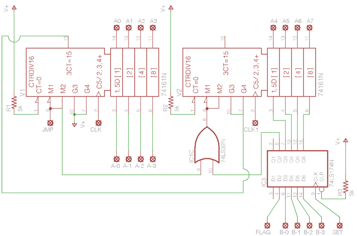
Schematics of TTL CPU
The third Eagle layout of the program counter has been completed, presenting a clearer design compared to the previous iterations, which were cluttered with intersecting wires, making it difficult to discern connections. This diagram is intended to facilitate understanding of...

Controlling Devices Through a Computer`s Parallel Port
This is a very easy and fun to build project that will allow you to control up to eight external devices through your computer's parallel port. You may for instance control different appliances such as lamps, computers, printers, TV sets,...

Adjustable TTL clock
The symmetry of the square-wave output is maintained by connecting the right side of resistor R2 through resistor R3 to the output of the third amplifier stage. This configuration alters the charging current to the capacitors in proportion to the...

Wisp628
Wisp628 is designed to be used as an in-circuit programmer only, hence no socket is provided for the target chip. Why use such a limited design, you might ask, an ex-circuit programmer with a ZIF socket can do the same...
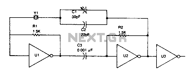
TTL oscillator
TTL inverter stages, U1 and U2, are cross-connected with a crystal Y1. A resistor in each stage biases the normally digital gates into a region where they operate as amplifiers. Inverter stage U3 is used as a buffer.
The circuit consists...

PC FM Radio Circuit
If familiar with programming languages such as C++, PASCAL, VISUAL BASIC, or DELPHI, it is possible to write a program that sends numbers from 0 to 255 through the parallel port (378 I) of a PC. This process checks the...

TTL signal levels using a serial port MAX232
A PC’s serial port provides signal lines that you can use to expand the number of input signals. With some additional circuitry tied to these lines, you can use the port to test digital TTL logic-level circuits. You just need...

Design Parallel Port Interface Project PCB
The following schematic illustrates the design of a Parallel Port Interface Circuit Diagram utilizing the 74HCT373. The 74HC/HCT373 are high-speed silicon-gate CMOS devices that are pin-compatible with low-power Schottky TTL (LSTTL). This parallel port interface circuit can drive 256 relays...

Simple ttl crystal oscillator
This simple and inexpensive crystal oscillator consists of one-third of a 7404 IC, four resistors, and a crystal. The inverters are biased into their linear regions by resistors R1 to R4, while the crystal provides the necessary feedback. Oscillation can...