


ATMEL 89C Series Flash Programmer
#AT89C
#flash programmer
#parallel port
#TTL
#PC interface
#programming
#microcontroller
#hardware
#DIY

Description: This programmer was designed in view of to be flexible, economical and easy to built, the programmer hardware utilizes the standard TTL series parts and no special components are used. The programmer is interfaced with the PC parallel port and there is no special requirement for the PC parallel port, so the older computers can also be used with this programmer. More: Figure 1 shows the circuit diagram of the Flash Programmer, the programmer is interfaced with the standard parallel port of the PC. As shown in the diagram U1 is used to control the data flow between controller and the pc, U3 latched the low order address.
The Flash Programmer circuit is designed to provide a straightforward and cost-effective solution for programming flash memory devices using a PC's parallel port. The use of standard TTL (Transistor-Transistor Logic) components ensures compatibility and ease of construction, making it accessible for hobbyists and engineers alike.
The circuit primarily consists of a few key integrated circuits and passive components that facilitate communication between the PC and the target flash memory. The central component, U1, functions as a data flow controller, managing the signals sent from the parallel port to the memory device. This IC is crucial for ensuring that the data is correctly interpreted and transmitted, allowing for reliable programming operations.
U3 serves a vital role in the circuit by latching the low-order address lines. This function is essential for addressing the specific memory locations within the flash device during the programming process. Proper latching of the address lines ensures that the programmer can access and write to the correct locations in the memory, which is critical for successful programming.
The design's flexibility allows it to interface with a wide range of flash memory types, making it a versatile tool for various applications. The straightforward nature of the circuit means that it can be assembled using commonly available components, thus minimizing costs and enhancing accessibility for users with different levels of expertise.
Overall, the Flash Programmer circuit is an efficient and economical solution for programming flash memory, leveraging the simplicity of TTL technology and the ubiquitous nature of the PC parallel port.This programmer was designed in view of to be flexible, economical and easy to built, the programmer hardware utilizes the standard TTL series parts and no special components are used. The programmer is interfaced with the PC parallel port and there is no special requirement for the PC parallel port, so the older computers can also be used with this programmer.
Figure 1 shows the circuit diagram of the Flash Programmer, the programmer is interfaced with the standard parallel port of the PC. As shown in the diagram U1 is used to control the data flow between controller and the pc, U3 latched the low order address
The Flash Programmer circuit is designed to provide a straightforward and cost-effective solution for programming flash memory devices using a PC's parallel port. The use of standard TTL (Transistor-Transistor Logic) components ensures compatibility and ease of construction, making it accessible for hobbyists and engineers alike.
The circuit primarily consists of a few key integrated circuits and passive components that facilitate communication between the PC and the target flash memory. The central component, U1, functions as a data flow controller, managing the signals sent from the parallel port to the memory device. This IC is crucial for ensuring that the data is correctly interpreted and transmitted, allowing for reliable programming operations.
U3 serves a vital role in the circuit by latching the low-order address lines. This function is essential for addressing the specific memory locations within the flash device during the programming process. Proper latching of the address lines ensures that the programmer can access and write to the correct locations in the memory, which is critical for successful programming.
The design's flexibility allows it to interface with a wide range of flash memory types, making it a versatile tool for various applications. The straightforward nature of the circuit means that it can be assembled using commonly available components, thus minimizing costs and enhancing accessibility for users with different levels of expertise.
Overall, the Flash Programmer circuit is an efficient and economical solution for programming flash memory, leveraging the simplicity of TTL technology and the ubiquitous nature of the PC parallel port.This programmer was designed in view of to be flexible, economical and easy to built, the programmer hardware utilizes the standard TTL series parts and no special components are used. The programmer is interfaced with the PC parallel port and there is no special requirement for the PC parallel port, so the older computers can also be used with this programmer.
Figure 1 shows the circuit diagram of the Flash Programmer, the programmer is interfaced with the standard parallel port of the PC. As shown in the diagram U1 is used to control the data flow between controller and the pc, U3 latched the low order address

Interfacing seven segment to microcontroller
The Tutorial shows how to interface 7-segment display to a microcontroller. Also explains how do display more than one 7-segment on same data lines using scanning method. 7 Seg displays are are basically 7 LED's. It will be much easier...

MCU controlled Bluetooth automation
The microcontroller used is 0822 zilog encore! 8k series (soic,28pin) as shown on the figure. Is a programmable microcontroller, the functions used are the GPIO and the UART of the chip. GPIO is used on led indicators, and the UART...

Microcontroller Relay Driver and Interface
Many microcontroller designs typically integrate various interfacing methods. A microcontroller (µC) system can be viewed as a system that reads from inputs.
Microcontroller systems are versatile platforms that facilitate the integration of multiple interfacing methods to interact with various peripherals and...
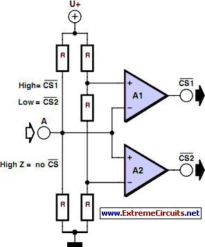
Multitasking Pins circuit
It is entirely logical that low-cost miniature microcontrollers have fewer pins than their larger counterparts, sometimes too few. Consideration has been given to how to economize on pins by making them perform the work of several. It was noted that...

Parallel port controls arbitrary-waveform generator
You can use the parallel port of your PC and a few additional components to generate a powerful, easy-to-use arbitrary-waveform generator. By using a Visual Basic program with the circuit in Figure 1, you can generate any waveform (for example,...

Microcontroller-based automatic night light circuit
While discussing an all-linear automatic night light circuit, it was mentioned that an MCU-based Automatic Night Light Controller (ANLC) was being tested. The firmware has been tweaked since then. Recently, the sensor was installed outdoors and connected to control 220VAC...
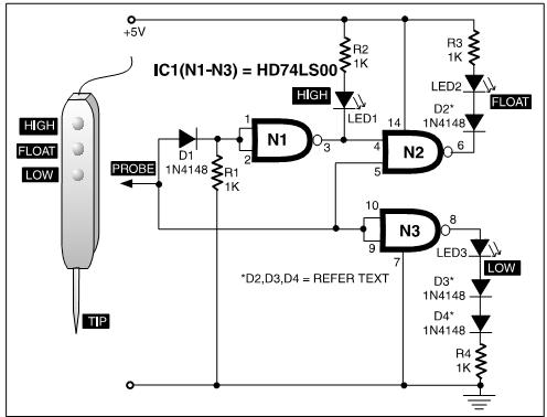
TTL Three - State Logic Probe PCB
A TTL logic probe is an essential tool for troubleshooting digital circuits. Various methods can be utilized to design a logic probe. The most common designs incorporate operational amplifiers, logic gates (OR, NOT, XOR), and transistors. The circuit described here...
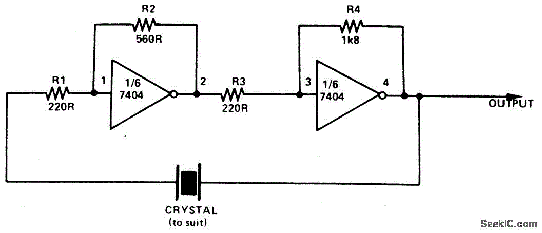
SIMPLE TTL CRYSTAL OSCILLATOR
This simple and inexpensive crystal oscillator consists of one-third of a 7404 hex inverter, four resistors, and a crystal. The inverters are biased into their linear regions by resistors R1 to R4, while the crystal provides the necessary feedback. Oscillation...

knight Rider
A light computer has been developed that simulates the scanning effect seen in the KITT car from the TV series Knight Rider. The design utilizes a microcontroller, specifically the PIC16F84A, instead of the commonly used CD4017 counter IC. This choice...