


Atmel 89C2051 prototype board
#Atmel 89C2051
#prototype board
#MAX232
#serial driver
#AVR
#u-controllers
#power supply
#user interface
#development board

Description: This single-sided prototyping board offers an economical solution for developing and testing projects utilizing Atmel's 20-pin series microcontrollers (89Cx051 & AVR). The circuit diagram of the prototyping board is illustrated in Figure 1. All port connections are accessible for user interaction within the prototyping area, including the power supply pins. A MAX232 serial driver is incorporated to provide a three-wire RS232 interface for connecting to a PC or other RS232 devices. Switch S1 facilitates a manual reset for the microcontroller. For AVR devices, components C6 and R2 must be swapped, as the AVR series features an active low reset input. Additionally, the Vcc point of reset switch S1 should be connected to GND instead of Vcc; the PCB includes provisions for selecting the reset type for switch S1.
The described single-sided prototyping board is designed to facilitate the development and testing of electronic projects centered around Atmel's 20-pin microcontrollers, specifically the 89Cx051 and AVR series. The layout allows for easy access to all necessary port connections, enabling straightforward user interaction and component integration. The inclusion of a MAX232 serial driver is essential for establishing a reliable RS232 communication link, which is crucial for interfacing with PCs or other RS232-compliant devices.
The manual reset functionality provided by switch S1 is a vital feature for debugging and testing purposes, allowing developers to reset the microcontroller as needed. It is important to note the specific requirements for AVR devices, which necessitate the swapping of components C6 and R2 due to their differing reset input characteristics. This modification ensures that the reset function operates correctly in an active low configuration, which is standard for AVR microcontrollers.
Moreover, the design accommodates flexibility in the reset configuration by allowing the user to select the appropriate reset type for switch S1. This adaptability is facilitated by dedicated provisions on the PCB, ensuring that developers can customize the board according to their specific project requirements. Overall, this prototyping board serves as a valuable tool for engineers and developers working with Atmel's microcontrollers, streamlining the process of project development and testing.This single sided proto board provides an economical solution for developing and testing the projects around Atmel 20 pin series u-controllers (89Cx051 & AVR). Figure 1 shows the circuit diagram of proto board. All port connections are available for user interface around the proto area including the power supply pins.
MAX232 serial driver is used to provide a 3 wire RS232 interface for connecting to the PC or other rs232 devices. Switch S1 provide a manual reset to u-controller. For AVR devices the C6 and R2 has to be interchanged, because AVR series have active low reset input also the Vcc point of reset switch S1 has to be connected to GND instead of Vcc, there is a provision on pcb for the selection of reset type for switch S1.
The described single-sided prototyping board is designed to facilitate the development and testing of electronic projects centered around Atmel's 20-pin microcontrollers, specifically the 89Cx051 and AVR series. The layout allows for easy access to all necessary port connections, enabling straightforward user interaction and component integration. The inclusion of a MAX232 serial driver is essential for establishing a reliable RS232 communication link, which is crucial for interfacing with PCs or other RS232-compliant devices.
The manual reset functionality provided by switch S1 is a vital feature for debugging and testing purposes, allowing developers to reset the microcontroller as needed. It is important to note the specific requirements for AVR devices, which necessitate the swapping of components C6 and R2 due to their differing reset input characteristics. This modification ensures that the reset function operates correctly in an active low configuration, which is standard for AVR microcontrollers.
Moreover, the design accommodates flexibility in the reset configuration by allowing the user to select the appropriate reset type for switch S1. This adaptability is facilitated by dedicated provisions on the PCB, ensuring that developers can customize the board according to their specific project requirements. Overall, this prototyping board serves as a valuable tool for engineers and developers working with Atmel's microcontrollers, streamlining the process of project development and testing.This single sided proto board provides an economical solution for developing and testing the projects around Atmel 20 pin series u-controllers (89Cx051 & AVR). Figure 1 shows the circuit diagram of proto board. All port connections are available for user interface around the proto area including the power supply pins.
MAX232 serial driver is used to provide a 3 wire RS232 interface for connecting to the PC or other rs232 devices. Switch S1 provide a manual reset to u-controller. For AVR devices the C6 and R2 has to be interchanged, because AVR series have active low reset input also the Vcc point of reset switch S1 has to be connected to GND instead of Vcc, there is a provision on pcb for the selection of reset type for switch S1.

avr ntp clock.
The Network Time Protocol (NTP) has transformed global timekeeping, allowing accurate time and date information from anywhere in the world. NTP is a straightforward UDP-based protocol that can be implemented in a microcontroller. While UDP and TCP servers have been...

AVR to LCD
If no characters are displayed on the LCD and the hardware and software have been verified as functional, adjust the LCD Contrast potentiometer until the characters become visible. To send an 8-bit character or command to the LCD via the...
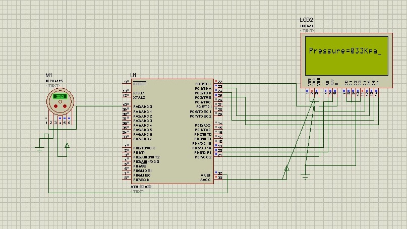
avr microcontroller project
H-Bridge circuit utilizing transistors for the bidirectional control of a DC motor. Integrated circuits (ICs) containing H-Bridges are employed to simplify the drive circuit. The L293D is a dual H-Bridge motor driver, allowing for the control of two DC motors...

8 MHz frequency meter using AVR microcontroller
This project measures the clock pulses supplied to the Timer input of the AVR microcontroller. The Bascom code counts the clock pulses over a duration of 1 second and displays the result.
The circuit for this project primarily consists of an...

Batteries charger & PSU - ideal for digital camerass
This circuit was designed for digital cameras, which are known to have significant power consumption. For instance, the Minolta E223 camera requires approximately 800 mA. In practice, this demand can be met using a mains power supply or high-capacity NiMH...

USB AVR In-System-Programmer (ISP)
Nowadays, USB is the most popular connection between PCs and peripherals such as AVR programmers, printers, scanners, etc. For that reason, it was necessary to modify an old serial AVR In-System-Programmer (ISP) to work with a USB connection. One solution...

AVR Microcontroller Programmer
This resource contains step-by-step information for creating an AVR microcontroller programmer, complete with a suitable circuit diagram. This programmer is capable of programming 8051, AT89XX, AT90XXXX, and 8031 family microcontrollers.
The AVR microcontroller programmer described is designed to facilitate the programming...

35W switching power supply circuit having a set-top box output of 5
A 35W switching power supply circuit designed for a set-top box output is depicted in Figure 5. It features five distinct voltage outputs: Uo1 (+30V, 100mA), Uo2 (+18V, 550mA), Uo3 (+5V, 2.5A), Uo4 (+3.3V, 3A), and Uo5 (-5V, 100mA). The...

Ridiculously Simple AVR AM Radio Transmitter
Create a rapid transmitter/receiver pair that can be found in most households. An AM or FM radio system is suitable since it is widely accessible. The design focuses on generating the required radio signal and modulating it effectively. After exploring...