


Atmel At90S2313 Countermeasures
#Atmel
#At90S2313
#frequency counter
#TTL
#LED display
#microcontroller
#HC TTL
#band indicator
#digital logic

Description: This project meets a specific need by utilizing a frequency counter built with basic TTL chips, predating the availability of CMOS HC versions. The design incorporates four chips: three HC TTLs and an Atmel AT90S2313 microcontroller. It features a five-digit LED display, with one digit functioning as a band indicator. Despite the LED display, the circuit consumes less than 50 mA of current and can count frequencies of at least 52 MHz. The highest signal source available in the lab was limited to 52 MHz; however, the typical clock frequency for the HC590 is approximately 35-40 MHz, suggesting that higher frequencies should be approached with caution. The concept originated from an article, likely from Circuit Cellar, which provided a quick and simple counter solution.
The implementation involves constructing an 8-bit data bus using the lower four bits of PORTD and the upper four bits of PORTB on the AT90S2313. This configuration is necessary to utilize the OC1 output on PB3 for gating the counter stage. The display consists of three-digit, common-cathode, seven-segment displays that are multiplexed by sending segment data from the data bus and selecting the active digit using an HC138 data selector controlled by three I/O lines from the AT90S2313. Two HC590 counters are employed to count input pulses, providing the count to the AT90S2313 via the data bus. Each counter can be read independently using the OE_L and OE_H lines, while the counters are reset using the CLR signal. The gating of the counters is managed by the OC1 signal from the AT90S2313, allowing for varying gate durations to facilitate autoranging and accommodate a wide frequency range.
The software for the counter is developed in C, prioritizing simplicity over speed, as high-speed operations are handled externally by the counters and Timer1 within the AT90S2313. The frequency measurement process is straightforward: the counters are enabled for 1 ms, and if the count exceeds 4096 (indicating frequencies above 4.096 MHz), the result is displayed, followed by a new count. If the count is below 4096, a longer gate time of 10 ms is employed for improved resolution, and the process is repeated. If the count remains below 4096, the system switches to 100 ms or down to 1 second to capture lower frequencies accurately.
This circuit design exemplifies a practical approach to frequency counting, leveraging both hardware and software components to achieve reliable performance across a range of input frequencies. The careful consideration of power consumption, display multiplexing, and gating techniques ensures that the device operates efficiently while providing accurate frequency measurements.This is another project which fullfills a need. I once built a frequency counter using plain TTL chips. That was long before the CMOS HC versions, even before LS was available. It uses only 4 chips - 3 HC TTL`s and an Atmel At90S2313 microcontroller. It has a 5 digit LED display plus one used as a band indicator. Even with the LED display, the cur rent consumption is less than 50 mA. It counts up to at least 52 MHz. I couldn`t find any signal source in the lab that could supply more than 52 MHz, so it may go a bit higher, but the fClock(typ) for the HC590 is about 35-40 MHz, so you shouldn`t really count (no pun intended) on more. I got the idea from an article I saw on the net. I think it was a Circuit Cellar article. I had a look at the code, and it sounded like a quick and simple counter solution. I don`t know what chips it used, as I never saw the schematic, but here`s my implementation : A 8-bit "databus" is constructed from the lower 4 bits of PORTD and the upper 4 bits of PORTB on the 2313.
This peculiar arrangement is necessary, as we need the OC1 output on PB3 for gating the counter stage. The displays are 3-digit 7-segment common-cathode displays. They are multiplexed by supplying the segment data from the databus, and selecting the current digit with a `HC138 dataselector, which is controlled by 3 I/O lines from the 2313.
The two `HC590 counters are counting the input pulses and supplies the count to the 2313 on the databus. Each counter can be read separately using the OE_L and OE_H lines. The counters are cleared using the CLR signal. The counters are gated using the OC1 (Output Compare 1) signal from the 2313. By varying the duration of the gate time, the counter can be made autoranging, and handle a large frequency span.
The software for the counter is written in C-code, as speed is not an issue. All high-speed handling is done by the external counters and the Timer1 in the 2313. The method of measuing a frequency is simple. First, the counters are enabled for 1 mS. If the count is larger than 4096 (4. 096 MHz), the count is shown on the display, and a new count is made. If less that 4096, we can get better resolution with a larger gate time, so we try 10 mS. Again, if the count is larger than 4096 (409. 6 KHz), the count is shown, otherwise we try 100mS, or down to 1 S.
The implementation involves constructing an 8-bit data bus using the lower four bits of PORTD and the upper four bits of PORTB on the AT90S2313. This configuration is necessary to utilize the OC1 output on PB3 for gating the counter stage. The display consists of three-digit, common-cathode, seven-segment displays that are multiplexed by sending segment data from the data bus and selecting the active digit using an HC138 data selector controlled by three I/O lines from the AT90S2313. Two HC590 counters are employed to count input pulses, providing the count to the AT90S2313 via the data bus. Each counter can be read independently using the OE_L and OE_H lines, while the counters are reset using the CLR signal. The gating of the counters is managed by the OC1 signal from the AT90S2313, allowing for varying gate durations to facilitate autoranging and accommodate a wide frequency range.
The software for the counter is developed in C, prioritizing simplicity over speed, as high-speed operations are handled externally by the counters and Timer1 within the AT90S2313. The frequency measurement process is straightforward: the counters are enabled for 1 ms, and if the count exceeds 4096 (indicating frequencies above 4.096 MHz), the result is displayed, followed by a new count. If the count is below 4096, a longer gate time of 10 ms is employed for improved resolution, and the process is repeated. If the count remains below 4096, the system switches to 100 ms or down to 1 second to capture lower frequencies accurately.
This circuit design exemplifies a practical approach to frequency counting, leveraging both hardware and software components to achieve reliable performance across a range of input frequencies. The careful consideration of power consumption, display multiplexing, and gating techniques ensures that the device operates efficiently while providing accurate frequency measurements.This is another project which fullfills a need. I once built a frequency counter using plain TTL chips. That was long before the CMOS HC versions, even before LS was available. It uses only 4 chips - 3 HC TTL`s and an Atmel At90S2313 microcontroller. It has a 5 digit LED display plus one used as a band indicator. Even with the LED display, the cur rent consumption is less than 50 mA. It counts up to at least 52 MHz. I couldn`t find any signal source in the lab that could supply more than 52 MHz, so it may go a bit higher, but the fClock(typ) for the HC590 is about 35-40 MHz, so you shouldn`t really count (no pun intended) on more. I got the idea from an article I saw on the net. I think it was a Circuit Cellar article. I had a look at the code, and it sounded like a quick and simple counter solution. I don`t know what chips it used, as I never saw the schematic, but here`s my implementation : A 8-bit "databus" is constructed from the lower 4 bits of PORTD and the upper 4 bits of PORTB on the 2313.
This peculiar arrangement is necessary, as we need the OC1 output on PB3 for gating the counter stage. The displays are 3-digit 7-segment common-cathode displays. They are multiplexed by supplying the segment data from the databus, and selecting the current digit with a `HC138 dataselector, which is controlled by 3 I/O lines from the 2313.
The two `HC590 counters are counting the input pulses and supplies the count to the 2313 on the databus. Each counter can be read separately using the OE_L and OE_H lines. The counters are cleared using the CLR signal. The counters are gated using the OC1 (Output Compare 1) signal from the 2313. By varying the duration of the gate time, the counter can be made autoranging, and handle a large frequency span.
The software for the counter is written in C-code, as speed is not an issue. All high-speed handling is done by the external counters and the Timer1 in the 2313. The method of measuing a frequency is simple. First, the counters are enabled for 1 mS. If the count is larger than 4096 (4. 096 MHz), the count is shown on the display, and a new count is made. If less that 4096, we can get better resolution with a larger gate time, so we try 10 mS. Again, if the count is larger than 4096 (409. 6 KHz), the count is shown, otherwise we try 100mS, or down to 1 S.

simple frequency counter circuit
The circuit illustrated below is designed for measuring frequency in Hertz (Hz). It is straightforward to construct, utilizing a single IC 4033 and a common cathode display as the main components. For measuring higher frequencies, typically in the range of...

Frequency counter up to 1MHZ
The MK50398 is one modern decimal counter up/down of six tens, with control of screen LED of seven segments and flip-flop of storage. Counter it can measure additive and abstractively. The IC MK50398 is ideal for manufacture frequency counter as...

microcontroller How does this power supply circuit work? (MCU + LM317)
The filter consisting of resistors R1, R2, and capacitor C1 integrates the PWM waveform. The purpose of the operational amplifier appears to be that of a non-inverting amplifier, with the gain determined by resistors R6 and R7. However, the need...

Digital frequency counter
The frequency counter is designed to measure the number of cycles per second of an incoming signal. A counting device is necessary for this purpose, and in electronic circuits, counter integrated circuits (ICs) are available for counting input pulses. The...

10Mhz Frequency Counter Circuit
The circuit comprises an ICM7208 seven-decade counter (U1), an ICM7207A oscillator controller (U2), and a CA3130 biFET operational amplifier (U3). Integrated circuit U1 counts input signals, decodes them into a 7-segment format, and outputs signals to drive a 7-digit display....

LED Volt Meter Circuit LM324
This circuit is a practical device that, when installed in a vehicle, displays the voltage of the car battery using an LED dot display. The meter circuit utilizes four comparators formed from a quad op-amp, specifically the LM324. The inverting...

Frequency counter BNC input schematic
This is a CMOS-compatible (and ideally also TTL-compatible) input that includes over-voltage and under-voltage protection. Schmitt triggers are utilized to accommodate inputs with long transition times. It has been verified to function at frequencies up to 30 MHz.
The described circuit...

POWER LINE MODEM FOR COMPUTER CONTROL
This circuit employs an 87C57 microcontroller along with several peripherals to convert X-10 power-line carrier-code formats from a personal computer for use with an X-10 power-line interface in a home-control system. Software details can be found in the reference.
The circuit...
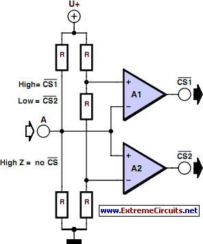
Multitasking Pins circuit
It is entirely logical that low-cost miniature microcontrollers have fewer pins than their larger counterparts, sometimes too few. Consideration has been given to how to economize on pins by making them perform the work of several. It was noted that...