


Basic circuit for PIC16F877A
#PIC16F877A
#basic circuit
#microcontroller
#electronics
#schematic
#components
#circuit design
#embedded systems

Description: To operate a microcontroller, basic components are required to support its functionality, which is referred to as a basic circuit. The components needed are common and readily available at any electronics store. This document presents the schematic of a basic circuit to operate a PIC16F877A microcontroller.
The basic circuit for operating a PIC16F877A microcontroller typically includes several essential components to ensure stable performance and reliable operation. The primary components include the microcontroller itself, a power supply, decoupling capacitors, a crystal oscillator, and input/output devices.
1. **Microcontroller**: The PIC16F877A is an 8-bit microcontroller from Microchip Technology. It features 40 pins, including digital I/O pins, analog inputs, and communication interfaces.
2. **Power Supply**: The microcontroller requires a stable power supply, typically ranging from 2.0V to 5.5V. A common choice is a 5V DC power supply. It is advisable to use a voltage regulator if the supply voltage exceeds this range.
3. **Decoupling Capacitors**: To filter out noise and stabilize the power supply, decoupling capacitors (usually 0.1µF ceramic capacitors) should be placed close to the power pins of the microcontroller. This helps prevent voltage fluctuations that could affect the operation of the microcontroller.
4. **Crystal Oscillator**: The PIC16F877A requires an external clock source for timing purposes. A crystal oscillator (commonly 4MHz or 20MHz) is often used along with two load capacitors (typically 22pF) to ensure proper oscillation frequency.
5. **Input/Output Devices**: Depending on the application, various input and output devices can be connected to the microcontroller. This may include switches, LEDs, sensors, and communication modules. Each device should be connected to the appropriate I/O pins on the microcontroller.
6. **Reset Circuit**: A reset circuit is essential for initializing the microcontroller. This can be achieved using a push-button switch connected to the MCLR pin, along with a pull-up resistor (typically 10kΩ) to ensure the pin remains high during normal operation.
7. **Programming Interface**: For programming the microcontroller, a suitable interface, such as ICSP (In-Circuit Serial Programming), should be included in the circuit. This typically involves connecting specific pins to a programmer device.
The schematic for the basic circuit will reflect these components, illustrating their interconnections and pin configurations. Proper layout and connection practices should be followed to ensure that the circuit operates efficiently and reliably.To operate a microcontroller, you need some basic components to support it and the circuit we call it basic circuit. The components needed are very common and you can find them at any electronics store out there. Here, i will share the schematic of basic circuit to operate a PIC16F877A microcontroller..
The basic circuit for operating a PIC16F877A microcontroller typically includes several essential components to ensure stable performance and reliable operation. The primary components include the microcontroller itself, a power supply, decoupling capacitors, a crystal oscillator, and input/output devices.
1. **Microcontroller**: The PIC16F877A is an 8-bit microcontroller from Microchip Technology. It features 40 pins, including digital I/O pins, analog inputs, and communication interfaces.
2. **Power Supply**: The microcontroller requires a stable power supply, typically ranging from 2.0V to 5.5V. A common choice is a 5V DC power supply. It is advisable to use a voltage regulator if the supply voltage exceeds this range.
3. **Decoupling Capacitors**: To filter out noise and stabilize the power supply, decoupling capacitors (usually 0.1µF ceramic capacitors) should be placed close to the power pins of the microcontroller. This helps prevent voltage fluctuations that could affect the operation of the microcontroller.
4. **Crystal Oscillator**: The PIC16F877A requires an external clock source for timing purposes. A crystal oscillator (commonly 4MHz or 20MHz) is often used along with two load capacitors (typically 22pF) to ensure proper oscillation frequency.
5. **Input/Output Devices**: Depending on the application, various input and output devices can be connected to the microcontroller. This may include switches, LEDs, sensors, and communication modules. Each device should be connected to the appropriate I/O pins on the microcontroller.
6. **Reset Circuit**: A reset circuit is essential for initializing the microcontroller. This can be achieved using a push-button switch connected to the MCLR pin, along with a pull-up resistor (typically 10kΩ) to ensure the pin remains high during normal operation.
7. **Programming Interface**: For programming the microcontroller, a suitable interface, such as ICSP (In-Circuit Serial Programming), should be included in the circuit. This typically involves connecting specific pins to a programmer device.
The schematic for the basic circuit will reflect these components, illustrating their interconnections and pin configurations. Proper layout and connection practices should be followed to ensure that the circuit operates efficiently and reliably.To operate a microcontroller, you need some basic components to support it and the circuit we call it basic circuit. The components needed are very common and you can find them at any electronics store out there. Here, i will share the schematic of basic circuit to operate a PIC16F877A microcontroller..

Microcontroller measures heart rate through fingertip
The reflected infrared (IR) signal detected by the photodiode is sent to a signal conditioning circuit, which filters out unwanted signals and amplifies the desired output.
The circuit begins with a photodiode that captures the reflected IR signals. The photodiode operates...
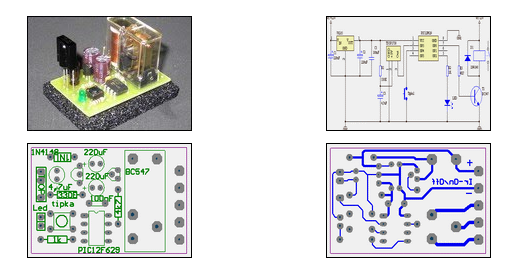
IR On/Off Switch Using Microcontroller
The ability to turn electrical devices ON or OFF using a remote control is a well-established concept, with numerous devices effectively performing this function.
To implement a remote control system for switching electrical devices, a typical schematic would include several key...

delay circuit for photography
This article outlines the construction of a simple microcontroller-based delay circuit designed for photographic applications such as drop or high-speed photography. It can control the trigger lag of cameras and flash units, generate periodic trigger pulses, or manage magnetic valves....

Hum Circuit
The kit employs an off-the-shelf microcontroller based on the AtMega328P-PU Arduino, along with a simplified version designed for ease of replication and modification by collaborators and students. This initiative aims to enable the fabrication of simplified microcontrollers for DIY synthetic...

Automatic Switch Project
Model railroad turnouts, often referred to as switches, can be controlled in various ways. The simplest method is manual control, operated by hand. Remote activation is typically achieved through pneumatic (air) or electrical means. The project discussed in these articles...

Talking Yoda head
The talking Yoda head consists of a Yoda mask and a microcontroller system to achieve the desired operation/effect. The basic operation of the project was specified as follows: The head was to be placed inside a closed box. Upon opening...

Layout Control Mother Board
The layout control motherboard is designed to facilitate the management of various sections of a layout. It features a microcontroller that connects to the MRNet bus and multiple slots for inexpensive control and sensor boards. All control and sensor boards...

delay
This article outlines the construction of a simple microcontroller-based delay circuit designed for photographic applications, such as drop or high-speed photography. It is capable of controlling the trigger lag for cameras and flash units, generating periodic trigger pulses, or managing...

Handy Cricket Hardware Description
This document presents an overview of the hardware design of the Handy Cricket.
The Handy Cricket is a compact electronic device designed for educational and recreational purposes, primarily aimed at children. The hardware design incorporates various components that work together to...