


Clock Controller circuit
#timer0 interrupt
#7-segment LED
#keypad scanning
#C language
#sink current driving
#relay
#opto-triac
#display interfacing
#keypad interfacing

Description: The Clock Controller was designed as an exemplary application of the C programming language to manage timer0 interrupts, control a 7-segment LED display, and perform keypad scanning. It offers a 1-bit sink current output suitable for driving devices such as relays or opto-triacs. Various projects that require interfacing with a 7-segment display and a keypad can derive insights from this Clock circuit and its software. Figure 1 illustrates the circuit diagram of the Clock Controller V1.1. Pins P1.0 to P1.7 are utilized to drive a common anode 7-segment LED with sink current. Pins P3.0 to P3.3 control the base pin of a 4-PNP transistor, specifically the 2N2907, also using sink current. The second 2-digit LED, connected to P3.2 and P3.3, is rotated 180 degrees relative to the first 2-digit LED, allowing the common cathode segment to blink for one second. Pins P3.0 to P3.3 are also connected to four momentary switches, while the remaining leg connects to input port P3.4. During the display and key switch scanning process, a logic '0' is sequentially shifted from P3.0 to P3.3 every 10 ms; if a key is pressed, P3.4 will go low. P3.7 serves as a 1-bit sink current output, with the circuit employing a 2N2907 transistor to drive a small 5V electromechanical relay. The program, named clock.c, was written in C and compiled using the Micro-C Compiler from Dunfield Development Systems, utilizing the TINY memory model. The hex file suitable for downloading via Easy-Downloader is clock.hex. It is recommended to use a zero-switch solid-state relay for driving heavy loads exceeding 10A, as most solid-state relays can be driven with input voltages ranging from 3 to 30 VDC without issues.
The Clock Controller circuit is designed for efficient operation in applications requiring timer control, display, and user input. The use of a common anode configuration for the 7-segment display allows for simplified control of the segments by grounding the appropriate pins. The implementation of the 2N2907 PNP transistors as switches for the display ensures that sufficient current is supplied to illuminate the segments while maintaining low power consumption.
The keypad scanning mechanism is executed through a systematic approach, where the microcontroller sequentially activates each pin connected to the keypad. This technique not only minimizes the number of required I/O pins but also allows for rapid detection of key presses. The logic '0' shifting every 10 ms ensures that the system remains responsive to user input while maintaining a stable display.
In terms of output control, the inclusion of a relay driven by a 2N2907 transistor provides a versatile solution for controlling external devices. The use of a solid-state relay for higher current applications further enhances the circuit's capability, allowing it to interface with various load types without mechanical wear associated with traditional relays.
Overall, the Clock Controller represents a well-rounded design that integrates software and hardware elements effectively, serving as a valuable reference for similar projects involving 7-segment displays, keypad interfaces, and relay control. The accompanying software, along with the hardware design, offers a comprehensive framework for developers and engineers looking to implement similar functionalities in their electronic circuits.The Clock Controller was designed to be an exemplary of using `C` language to control timer0 interrupt, 7-segment LED and keypad scanning. It provides 1-bit sink current driving output, for driving a relay, opto-triac, say. Many projects requiring 7-segment display and keypad interfacing may get the idea from the Clock circuit and software.
Fi gure 1 depicts a circuit diagram of the Clock Controller V1. 1. P10-P1. 7 drives 7-segment common anode LED with sink current. P3. 0-P3. 3 also drives a base pin of 4-PNP transistor, 2n2907 with sink current. As shown in the figure, the 2nd 2-digit LED that connected to P3. 2 and P3. 3 is rotated 180 degrees to the 1st 2-digit allowing the pt. segment to be used for 1 second blinking. P3. 0-P3. 3 also connects four momentary switchs while the other legs are tied to input port P3. 4. During display and key switch scanning, a logic `0` is shifted from P3. 0 to P3. 3 every 10ms, if there was a key pressed, P3. 4 then became low. P3. 7 is a 1-bit sink current driving, an example in the circuit uses a 2n2907 to drive a small electromechanical relay 5V, say. The program clock. c was written in ‘C ’ language and was complied by Micro-C Compiler from Dunfiled Development Systems.
The memory model is TINY. The hex file of clock. c suitable for downloading by Easy-Downloader is clock. hex. I suggest to use a zero switch solid-state relay for driving heavy loads (>10A). Most solid state relays`s input can be drived with 3-30Vdc without any problems.
The Clock Controller circuit is designed for efficient operation in applications requiring timer control, display, and user input. The use of a common anode configuration for the 7-segment display allows for simplified control of the segments by grounding the appropriate pins. The implementation of the 2N2907 PNP transistors as switches for the display ensures that sufficient current is supplied to illuminate the segments while maintaining low power consumption.
The keypad scanning mechanism is executed through a systematic approach, where the microcontroller sequentially activates each pin connected to the keypad. This technique not only minimizes the number of required I/O pins but also allows for rapid detection of key presses. The logic '0' shifting every 10 ms ensures that the system remains responsive to user input while maintaining a stable display.
In terms of output control, the inclusion of a relay driven by a 2N2907 transistor provides a versatile solution for controlling external devices. The use of a solid-state relay for higher current applications further enhances the circuit's capability, allowing it to interface with various load types without mechanical wear associated with traditional relays.
Overall, the Clock Controller represents a well-rounded design that integrates software and hardware elements effectively, serving as a valuable reference for similar projects involving 7-segment displays, keypad interfaces, and relay control. The accompanying software, along with the hardware design, offers a comprehensive framework for developers and engineers looking to implement similar functionalities in their electronic circuits.The Clock Controller was designed to be an exemplary of using `C` language to control timer0 interrupt, 7-segment LED and keypad scanning. It provides 1-bit sink current driving output, for driving a relay, opto-triac, say. Many projects requiring 7-segment display and keypad interfacing may get the idea from the Clock circuit and software.
Fi gure 1 depicts a circuit diagram of the Clock Controller V1. 1. P10-P1. 7 drives 7-segment common anode LED with sink current. P3. 0-P3. 3 also drives a base pin of 4-PNP transistor, 2n2907 with sink current. As shown in the figure, the 2nd 2-digit LED that connected to P3. 2 and P3. 3 is rotated 180 degrees to the 1st 2-digit allowing the pt. segment to be used for 1 second blinking. P3. 0-P3. 3 also connects four momentary switchs while the other legs are tied to input port P3. 4. During display and key switch scanning, a logic `0` is shifted from P3. 0 to P3. 3 every 10ms, if there was a key pressed, P3. 4 then became low. P3. 7 is a 1-bit sink current driving, an example in the circuit uses a 2n2907 to drive a small electromechanical relay 5V, say. The program clock. c was written in ‘C ’ language and was complied by Micro-C Compiler from Dunfiled Development Systems.
The memory model is TINY. The hex file of clock. c suitable for downloading by Easy-Downloader is clock. hex. I suggest to use a zero switch solid-state relay for driving heavy loads (>10A). Most solid state relays`s input can be drived with 3-30Vdc without any problems.

Relay protection circuit
Operating power protection devices can be categorized into two types: DC power supply operation and AC operation. AC operating power is favored due to its lower investment costs, simpler operation, and reliable secondary circuit maintenance, making it widely used in...

Relay pull-in timer circuit in time process
The circuit features a two-stage structure with a timing range of approximately 0.5 to 12 seconds, while in a specified configuration, the timing range extends from 1 to 160 seconds. The transformer parameters include an iron core made of M42/15.7...

Relay Coil Energy Saver
Some relays may become warm if they remain energized for an extended period. The circuit presented here will actuate the relay as before but will reduce the hold current through the relay coil by approximately 50%, significantly decreasing heat dissipation...
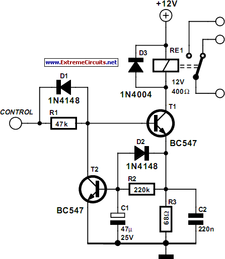
Energy Saver Relay Coil circuit and explanation
Some relays will become warm if they remain energized for some time. The circuit shown here will actuate the relay as before but then reduce the hold current through the relay coil by about 50%, thus considerably reducing the amount...

Control Circuits
This low current relay circuit is designed for use in battery-operated electronic devices. Its operating current is in microamperes (µA). This is achieved by using a bistable relay and incorporating additional components to enable the relay to function like a...

relay circuit
The intended result is for the relay to oscillate and the LEDs to flash when the button is pressed. However, when the button is pressed, the leftmost LED lights constantly, and nothing else happens. There is voltage across the left...

Multi Switch Controlled Relay
A Multi Switch Controlled Relay circuit is utilized to manage home appliances, featuring a circuit diagram that outlines the application of a multi switch-controlled relay using a single integrated circuit (IC) for various control functions.
The Multi Switch Controlled Relay circuit...
Reducing Relay Power Consumption
This circuit demonstrates that microprocessors, personal computers, and the latest ultra-accurate digital-to-analog converters (DACs) are excessive for the task of sequentially controlling four relays.
The circuit utilizes a simple microcontroller or a basic timer IC to manage the operation of four...

8 Channel LPT Relay Circuit
This circuit utilizes a Power Battery Terminal (PBT) to facilitate simple relay output and auxiliary power connections. An LED on each channel serves to indicate the status of the relay. Berg pins are provided for connecting power and trigger voltage....