


flight computer
#flight computer
#weight reduction
#single board design
#battery operation
#PCB mounting
#small components
#opto-coupler removal
#microcontroller

Description: The design modifications were primarily selected to enhance the system's weight efficiency. The majority of weight reduction was achieved through the implementation of a single board design, transitioning to single battery operation, and directly mounting the battery onto the PCB. Additional minor weight savings were realized by utilizing smaller components. The opto-coupler has been eliminated, allowing the microcontroller to directly drive the actuator transistor. A snubber diode has been incorporated across the motor, along with a small capacitor to mitigate noise. Furthermore, a capacitor has been added across the power rails of the microcontroller. The software modifications included disabling the brown-out reset feature on the microcontroller to prevent it from resetting due to noise on the power rails. The "P" display during parachute deployment has been substituted with a "-" to reduce power consumption from the battery while the motor is operational. The launch detection switch is now a smaller micro-switch, activated by a large nail sliding within a guide, which minimizes unnecessary shocks to the armature during landing. In version 1.2, the weight was glued to the armature, which caused the armature to disengage from the switch upon landing. The new configuration is also more compact. The "power," "program," and "arm" switches have been positioned closely together to facilitate access through a smaller opening in the rocket body, thereby streamlining the rocket and reducing drag. Due to forthcoming experiments, the range of selectable delays has been expanded. A table detailing the range of delays settable with version 1.3 follows.
The revised design focuses on optimizing the overall weight and functionality of the system while maintaining robust performance. The single board design significantly reduces the complexity and weight of the assembly, allowing for a more efficient integration of components. The direct mounting of the battery onto the PCB eliminates additional connectors and wiring, which can contribute to weight and potential failure points.
The removal of the opto-coupler simplifies the circuit and reduces the number of components, thus improving reliability. Directly driving the actuator transistor with the microcontroller enhances response time and reduces latency in actuator control. The addition of the snubber diode across the motor protects against voltage spikes that can occur during motor operation, while the capacitor aids in filtering out high-frequency noise, ensuring stable operation of the microcontroller.
The decision to disable the brown-out reset feature is particularly crucial in environments where electrical noise may be present. This modification ensures that the microcontroller remains operational despite transient disturbances, which is vital for maintaining control during critical phases of operation.
The redesigned launch detection mechanism, utilizing a micro-switch activated by a sliding nail, provides a more reliable and shock-resistant solution. This change addresses previous issues where the armature could disengage upon impact, thereby enhancing the overall durability of the system during deployment.
The compact arrangement of the power, program, and arm switches not only simplifies user interaction but also contributes to aerodynamic efficiency by minimizing the profile of the rocket. The expansion of the selectable delay range is an important enhancement that allows for greater flexibility in operational timing, accommodating a wider variety of experimental setups.
Overall, these design improvements reflect a comprehensive approach to optimizing the system for performance, reliability, and ease of use in a compact form factor.The design changes were primarily chosen to improve weight of the system. The majority of weight savings were due to having a single board design, switching to single battery operation and mounting the battery directly on the PCB. Other small weight improvements included the use of smaller components. The opto-coupler has been removed and the micr o-controller directly drives the actuator transistor. A snubber diode has been added across the motor as well as a small capacitor to reduce noise. A capacitor has also been added across the micro-controller`s power rails. The software changes included disabling the brown-out reset on the micro-controller to prevent it from resetting when there was a bit of noise on the power rails. The "P" display during parachute deployment has been replaced with a "-" to reduce the amount of power drawn from the battery while the motor is in operation.
The launch detect switch is a smaller micro-switch and is activated by a large nail that slides within a guide. This helps prevent unnecessary shocks on the armature during landing. With the weight glued to the armature in V1. 2 it was possible for the armature to pop out of the switch on landing. The new arrangement is also more compact. The "power", "program" and "arm" switches have all been placed close together to allow them to be accessible from a much smaller hole in the rocket body.
This helps streamline the rocket reducing drag. Due to upcoming experiments the range of selectable delays has also been increased. The following table gives the range of delays settable with version 1. 3.
The revised design focuses on optimizing the overall weight and functionality of the system while maintaining robust performance. The single board design significantly reduces the complexity and weight of the assembly, allowing for a more efficient integration of components. The direct mounting of the battery onto the PCB eliminates additional connectors and wiring, which can contribute to weight and potential failure points.
The removal of the opto-coupler simplifies the circuit and reduces the number of components, thus improving reliability. Directly driving the actuator transistor with the microcontroller enhances response time and reduces latency in actuator control. The addition of the snubber diode across the motor protects against voltage spikes that can occur during motor operation, while the capacitor aids in filtering out high-frequency noise, ensuring stable operation of the microcontroller.
The decision to disable the brown-out reset feature is particularly crucial in environments where electrical noise may be present. This modification ensures that the microcontroller remains operational despite transient disturbances, which is vital for maintaining control during critical phases of operation.
The redesigned launch detection mechanism, utilizing a micro-switch activated by a sliding nail, provides a more reliable and shock-resistant solution. This change addresses previous issues where the armature could disengage upon impact, thereby enhancing the overall durability of the system during deployment.
The compact arrangement of the power, program, and arm switches not only simplifies user interaction but also contributes to aerodynamic efficiency by minimizing the profile of the rocket. The expansion of the selectable delay range is an important enhancement that allows for greater flexibility in operational timing, accommodating a wider variety of experimental setups.
Overall, these design improvements reflect a comprehensive approach to optimizing the system for performance, reliability, and ease of use in a compact form factor.The design changes were primarily chosen to improve weight of the system. The majority of weight savings were due to having a single board design, switching to single battery operation and mounting the battery directly on the PCB. Other small weight improvements included the use of smaller components. The opto-coupler has been removed and the micr o-controller directly drives the actuator transistor. A snubber diode has been added across the motor as well as a small capacitor to reduce noise. A capacitor has also been added across the micro-controller`s power rails. The software changes included disabling the brown-out reset on the micro-controller to prevent it from resetting when there was a bit of noise on the power rails. The "P" display during parachute deployment has been replaced with a "-" to reduce the amount of power drawn from the battery while the motor is in operation.
The launch detect switch is a smaller micro-switch and is activated by a large nail that slides within a guide. This helps prevent unnecessary shocks on the armature during landing. With the weight glued to the armature in V1. 2 it was possible for the armature to pop out of the switch on landing. The new arrangement is also more compact. The "power", "program" and "arm" switches have all been placed close together to allow them to be accessible from a much smaller hole in the rocket body.
This helps streamline the rocket reducing drag. Due to upcoming experiments the range of selectable delays has also been increased. The following table gives the range of delays settable with version 1. 3.

Microcontroller Voltmeter / Ammeter with LCD
The rectifier bridge voltage is determined by the U2 element; refer to its datasheet for the maximum voltage specifications. The minimum voltage at this pin should not fall below approximately 9V, or 6.5V if low-dropout type U2 and U3 voltage...

MICROCONTROLLER BASED AUTOMATIC ROOM LIGHT CONTROLLER
This project involves an automatic room light controller with a bidirectional visitor counter using a microcontroller. It is designed to manage room lighting and accurately count the number of individuals present. When a person enters the room, the counter increments...

MCU controlled Bluetooth automation
The microcontroller used is 0822 zilog encore! 8k series (soic,28pin) as shown on the figure. Is a programmable microcontroller, the functions used are the GPIO and the UART of the chip. GPIO is used on led indicators, and the UART...

DIAL ALARM-1
This is the lowest cost dialing alarm on the market and shows what can be done with an 8-pin microcontroller. The complete circuit is shown below. You cannot see all the features of this project by looking at the circuit...
Microcontroller Programming 2
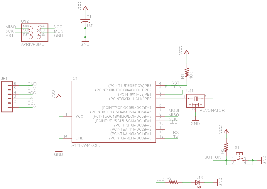
For this week's assignment, a chip design was provided, and the task was to incorporate a button and an LED (light-emitting diode). The objective was to fabricate the chip and program it to interact with the light and button. Given...

Microcontroller Backup Thin Film Batteries
Cymbet Corporation provides rechargeable solid-state batteries designed for advanced microcontroller power backup applications. The company is recognized as a leader in thin-film energy storage technology.
Cymbet Corporation's rechargeable solid-state batteries are engineered to deliver reliable power solutions for microcontrollers, which are...
measurement conductance cell constant
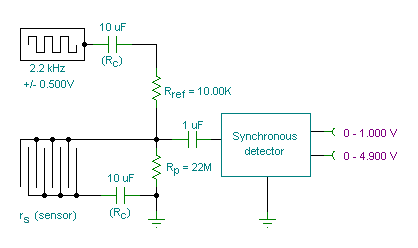
A small transmitter board interfaces with a microcontroller and conductivity probe to measure liquid conductance and conductivity. Precise equations and measurements are provided for this microcontroller-controlled conductivity meter.
The described circuit consists of a compact transmitter board that serves as an...

microcontroller Generate a reset signal from a falling edge trigger
The microcontroller design features the microcontroller (MCU) in hibernation mode, which can only be awakened by a pulse (high-low-high) signal on the reset pin (active low). An accelerometer or an external real-time clock (RTC) serves as the wake-up source. The...

Microcontroller interfacing with RS 232
Standard serial interfacing of a microcontroller (TTL) with a PC or any RS232C standard device requires a TTL to RS232 level converter. A MAX232 is used for this purpose. It provides a 2-channel RS232C port and requires external 10µF capacitors.
The...