


Implementing A Sewing Machine Controller With An Mc9rs08ka2 Microcontroller
#MC9RS08KA2
#MIC2199
#synchronous buck
#switching regulator
#voltage regulator
#N-Channel
#20A output
#4.5V-32V input
#0.8V-6V output
#300kHz switching
Description: The MIC2199 is a synchronous buck switching regulator controller. It features an all N-Channel synchronous architecture and powerful output drivers that enable a maximum output current capability of 20A. The device operates with an input voltage range of 4.5V to 32V and can be programmed to output voltages from 0.8V to 6V. With a switching frequency of 300kHz, it allows the use of smaller inductors. The external COMP pin facilitates the use of various output capacitors for optimal transient response. To minimize the pin count, the MIC2199 does not include an external soft-start pin, which typically helps reduce inrush current by delaying and controlling the output voltage rise time through a connected capacitor. Figure 1 illustrates the output voltage waveform for a standard MIC2199 circuit, showing a rise time of approximately 120 µs and an output voltage overshoot for VIN = 12V, VOUT = 3.3V, and ILOAD = 0A. Figure 2 presents a simple and cost-effective method to implement external soft-start on the MIC2199 using a capacitor (C1) and a 1N4148 diode between the VOUT and FB pins.
The MIC2199 synchronous buck switching regulator controller is designed to deliver high efficiency and robust performance in various applications, including power management for microcontrollers and other digital devices. The all N-Channel synchronous architecture significantly reduces conduction losses, making it suitable for high current applications. The ability to program the output voltage between 0.8V and 6V provides flexibility for different load requirements, while the wide input voltage range allows compatibility with various power sources.
The 300kHz switching frequency not only enables the use of smaller inductors but also contributes to the overall compactness of the circuit design. The external COMP pin is an essential feature, allowing designers to optimize the transient response by selecting appropriate output capacitors based on the application's specific needs. This adaptability is crucial in ensuring stable operation under varying load conditions.
While the absence of an external soft-start pin may initially seem limiting, the proposed method of implementing soft-start through the use of a capacitor and diode provides an effective solution. By connecting a capacitor (C1) and a 1N4148 diode between the VOUT and FB pins, the output voltage can be gradually ramped up, minimizing inrush current and preventing potential damage to connected components.
The output voltage waveform depicted in Figure 1 serves as a valuable reference for evaluating the performance of the MIC2199 in real-world applications. The observed overshoot and rise time characteristics are critical factors that engineers must consider when designing circuits to ensure reliability and efficiency. Overall, the MIC2199 is a versatile and powerful solution for applications requiring efficient voltage regulation and high output current capabilities.The MIC2199 is a synchronous buck switching Regulator controller. An all N-Channel synchronous architecture and powerful output drivers allow up to a 20A output current ca- pability. The MIC2199 operates from a 4. 5V to a 32V input and CAN be programmed for output voltage from 0. 8V to 6V. The 300kHz switching frequency allows the use of smaller ind uctor and the external COMP pin allows different output capacitor to be used for optimum transient response. To keep the pin count to a bare minimum, the MIC2199 does not offer an external soft-start pin that allow to reduce inrush current by delaying and slowing the output voltage rise time by connecting a capacitor on this pin.
Figure 1 shows the output voltage waveform for a stan- dard MIC2199 circuit that takes about 120 µs and exhibits an output voltage overshoot for VIN = 12V, VOUT = 3. 3V, I LOAD = 0A. Figure 2 shows a simple and inexpensive way of implementing external soft-start on the MIC2199 by using a capacitor, C1 and a Diode 1N4148 between VOUT and FB pins.
The MIC2199 synchronous buck switching regulator controller is designed to deliver high efficiency and robust performance in various applications, including power management for microcontrollers and other digital devices. The all N-Channel synchronous architecture significantly reduces conduction losses, making it suitable for high current applications. The ability to program the output voltage between 0.8V and 6V provides flexibility for different load requirements, while the wide input voltage range allows compatibility with various power sources.
The 300kHz switching frequency not only enables the use of smaller inductors but also contributes to the overall compactness of the circuit design. The external COMP pin is an essential feature, allowing designers to optimize the transient response by selecting appropriate output capacitors based on the application's specific needs. This adaptability is crucial in ensuring stable operation under varying load conditions.
While the absence of an external soft-start pin may initially seem limiting, the proposed method of implementing soft-start through the use of a capacitor and diode provides an effective solution. By connecting a capacitor (C1) and a 1N4148 diode between the VOUT and FB pins, the output voltage can be gradually ramped up, minimizing inrush current and preventing potential damage to connected components.
The output voltage waveform depicted in Figure 1 serves as a valuable reference for evaluating the performance of the MIC2199 in real-world applications. The observed overshoot and rise time characteristics are critical factors that engineers must consider when designing circuits to ensure reliability and efficiency. Overall, the MIC2199 is a versatile and powerful solution for applications requiring efficient voltage regulation and high output current capabilities.The MIC2199 is a synchronous buck switching Regulator controller. An all N-Channel synchronous architecture and powerful output drivers allow up to a 20A output current ca- pability. The MIC2199 operates from a 4. 5V to a 32V input and CAN be programmed for output voltage from 0. 8V to 6V. The 300kHz switching frequency allows the use of smaller ind uctor and the external COMP pin allows different output capacitor to be used for optimum transient response. To keep the pin count to a bare minimum, the MIC2199 does not offer an external soft-start pin that allow to reduce inrush current by delaying and slowing the output voltage rise time by connecting a capacitor on this pin.
Figure 1 shows the output voltage waveform for a stan- dard MIC2199 circuit that takes about 120 µs and exhibits an output voltage overshoot for VIN = 12V, VOUT = 3. 3V, I LOAD = 0A. Figure 2 shows a simple and inexpensive way of implementing external soft-start on the MIC2199 by using a capacitor, C1 and a Diode 1N4148 between VOUT and FB pins.

voltage regulator circuit with pass
This is a simple design for a voltage regulator circuit using a pass transistor. The design is built around the LM317T. The output current of the LM317T can be increased by incorporating an additional power transistor to share a portion...

Mobile voltage regulator
This simple mobile voltage regulator circuit may save your two-meter or CB transceiver if the voltage regulator fails. The 2N3055 should be heat-sinked if the current drawn by the rig exceeds 2 A during transmission. This circuit will do little...

Voltage Regulator Calculation
Before designing an adjustable voltage regulator into a circuit or performing a redesign, it is essential to calculate the values for two resistors. While this calculation is straightforward, locating the appropriate resistors may present challenges. Fortunately, a technique exists to...

DIY Satellite Finder Circuit
A circuit has been identified that integrates a voltage regulator and filter to isolate the voltage supplied by the receiver for powering an operational amplifier (op-amp) that drives a meter. Additionally, the circuit isolates the carrier frequency from the satellite,...
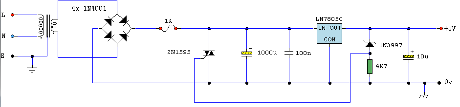
Logic PSU With Over-Voltage Protection
A simple 5 Volt regulated power supply unit (PSU) featuring overvoltage protection. This 5 Volt regulated power supply is designed for TTL and 74LS series integrated circuits.
The 5 Volt regulated power supply unit is an essential component in electronic designs...

Three-rail-power-supply
This circuit generates three supply voltages using a minimal number of components. Diodes D2 and D3 perform full-wave rectification, alternately charging capacitor C2 during both halves of the AC cycle. Meanwhile, diode D1 in conjunction with capacitor C1, and diode...

Self switching Power Supply
Self-switching power supply. One of the main features of the regulated power supply circuit being presented is that, although a fixed-voltage regulator LM7805 is used in the circuit, its.
The self-switching power supply circuit utilizes the LM7805 voltage regulator to maintain...

2.5V voltage regulator circuit
A 2.5V voltage regulator circuit is illustrated, which is part of a computer's motherboard. The circuit employs an oscillation circuit with the RT9202 control core chip, converting a 5V input supply into a regulated +2.5V output voltage, with the chip's...

Stable Filament Power Supply Circuit
The circuit diagram illustrates a voltage regulator designed from discrete components to meet specific voltage requirements. It provides two sets of component values for output voltages of 6.3 V (upper) and 12.6 V (lower). The components used include BC547 and...