


interfacing touch panel with arm7 friendly

Description: A touch screen is an electronic visual display capable of detecting the presence and location of a touch within its display area. This term typically refers to the interaction with the device's display using a finger or hand, although touch screens can also recognize other passive objects like a stylus. The interfacing of the touch panel with a microcontroller is illustrated in Figure 1.
To read the position of a touch, the touch position must be read sequentially, meaning the X position is read first, followed by the Y position. This is accomplished by connecting the X1 and Y2 pins of the touch screen to the ADC multiplexed GPIO pins of the microcontroller, while the X2 and Y1 pins are connected to standard GPIO pins. Interfacing a touch screen with a microcontroller requires two or more channels of an Analog-to-Digital Converter (ADC) since the touch screen outputs data as an analog voltage on two distinct pins, which are used to determine the touch position. The ADC input pins of the microcontroller should also be configurable as General Purpose I/O (GPIO).
The ARM7 LPC2148 Evaluation board features four touch panel connections linked to I/O port lines (P1.20, P1.21, P0.29, and P0.30) to facilitate touch panel output. The interfacing program for the touch panel with the LPC2148 is straightforward, allowing for text display on a 128 x 64 GLCD module upon a touch event. Some delays may occur during the execution of single commands or data. To compile the provided C code, the KEIL software must be properly set up, and a project with the correct settings must be created. The C file should be added to this project in KEIL.
For development or debugging without hardware setup, the code must be compiled to generate a HEX file. In debugging mode, it is possible to check the port output without the microcontroller board. The LPC2148 Evaluation Board requires a +3.3V power supply, with the touch screen connected to the LPC2148 Board. Once the program is downloaded onto the LPC2148 Evaluation Board, the screen will await a touch input. When the screen is touched, the output is activated. If there is no response from the touch screen, it is advisable to verify the jumper connections and adjust the trim pot level. Alternatively, debugging mode in KEIL can be utilized for troubleshooting. For additional debugging details, instructional videos are available through the provided link.
The electronic schematic for this setup would include the following components: a touch screen interfaced with the LPC2148 microcontroller, which is connected to a power supply of +3.3V. The touch screen's X1 and Y2 pins are routed to the ADC multiplexed GPIO pins of the LPC2148, while the X2 and Y1 pins are connected to standard GPIO pins. The schematic should also illustrate the connections to the GLCD module, detailing how the microcontroller communicates with the display to render output based on touch inputs. Proper labeling of pins and connections will ensure clarity in the schematic. Additionally, the configuration of the ADC channels must be indicated, as well as any necessary pull-up or pull-down resistors that may be required for stable operation. The schematic should also include annotations for potential adjustments, such as trim pot level settings, to facilitate troubleshooting and ensure optimal performance of the touch interface.A touch screen is an electronic visual display that can detect the presence and location of a touch within the display area. The term generally refers to touching the display of the device with a finger or hand. Touch screens can also sense other passive objects, such as a stylus. Fig. 1 shows how to interface the touch panel into microcontroller. To read the position of the touch, we have to first read touch position sequentially i. e. first read X position and then read the Y position. To do this, connect X1 and Y2 pins of touch screen to ADC multiplexed GPIO pins of the controller. And connect X2 and Y1 pins of touch screen to simple GPIO pins of the microcontroller. To Interface touch screen with a microcontroller, we will need a two or more channels of Analog-to-Digital converter. This is needed because, the touch screen will provide data in terms of an analog voltage on two different pins, using which, we have to determine position of the touch.
Also, ADC input pins of the microcontroller should be configurable as General Purpose I/O (GPIO). The ARM7 LPC2148 Evaluation board has four numbers of Touch panel connections, connected with I/O Port lines (P1. 20 P1. 21 && P0. 29 P0. 30) to make touch panel output. The Interfacing touch panel with LPC2148 program is very simple and straight forward, that display a text in 128 X 64 GLCD module when touch the touch panel.
Some delay is occurring when a single command / data is executed. To compile the above C code you need the KEIL software. They must be properly set up and a project with correct settings must be created in order to compile the code. To compile the above code, the C file must be added to the project. In Keil, you want to develop or debug the project without any hardware setup. You must compile the code for generating HEX file. In debugging Mode, you want to check the port output without microcontroller Board. Give +3. 3V power supply to LPC2148 Evaluation Board; the Touch screen is connected with microcontroller LPC2148 Board.
When the program is downloading into LPC2148 in Evaluation Board, the screen should wait for a touch. When you are touch the screen, the output is enabled. If you not getting any reactions from Touch screen, then you just check the jumper connections & adjust the trim pot level.
Otherwise you just check it with debugging mode in Keil. If you want to see more details about debugging just see the videos in below link.
To read the position of a touch, the touch position must be read sequentially, meaning the X position is read first, followed by the Y position. This is accomplished by connecting the X1 and Y2 pins of the touch screen to the ADC multiplexed GPIO pins of the microcontroller, while the X2 and Y1 pins are connected to standard GPIO pins. Interfacing a touch screen with a microcontroller requires two or more channels of an Analog-to-Digital Converter (ADC) since the touch screen outputs data as an analog voltage on two distinct pins, which are used to determine the touch position. The ADC input pins of the microcontroller should also be configurable as General Purpose I/O (GPIO).
The ARM7 LPC2148 Evaluation board features four touch panel connections linked to I/O port lines (P1.20, P1.21, P0.29, and P0.30) to facilitate touch panel output. The interfacing program for the touch panel with the LPC2148 is straightforward, allowing for text display on a 128 x 64 GLCD module upon a touch event. Some delays may occur during the execution of single commands or data. To compile the provided C code, the KEIL software must be properly set up, and a project with the correct settings must be created. The C file should be added to this project in KEIL.
For development or debugging without hardware setup, the code must be compiled to generate a HEX file. In debugging mode, it is possible to check the port output without the microcontroller board. The LPC2148 Evaluation Board requires a +3.3V power supply, with the touch screen connected to the LPC2148 Board. Once the program is downloaded onto the LPC2148 Evaluation Board, the screen will await a touch input. When the screen is touched, the output is activated. If there is no response from the touch screen, it is advisable to verify the jumper connections and adjust the trim pot level. Alternatively, debugging mode in KEIL can be utilized for troubleshooting. For additional debugging details, instructional videos are available through the provided link.
The electronic schematic for this setup would include the following components: a touch screen interfaced with the LPC2148 microcontroller, which is connected to a power supply of +3.3V. The touch screen's X1 and Y2 pins are routed to the ADC multiplexed GPIO pins of the LPC2148, while the X2 and Y1 pins are connected to standard GPIO pins. The schematic should also illustrate the connections to the GLCD module, detailing how the microcontroller communicates with the display to render output based on touch inputs. Proper labeling of pins and connections will ensure clarity in the schematic. Additionally, the configuration of the ADC channels must be indicated, as well as any necessary pull-up or pull-down resistors that may be required for stable operation. The schematic should also include annotations for potential adjustments, such as trim pot level settings, to facilitate troubleshooting and ensure optimal performance of the touch interface.A touch screen is an electronic visual display that can detect the presence and location of a touch within the display area. The term generally refers to touching the display of the device with a finger or hand. Touch screens can also sense other passive objects, such as a stylus. Fig. 1 shows how to interface the touch panel into microcontroller. To read the position of the touch, we have to first read touch position sequentially i. e. first read X position and then read the Y position. To do this, connect X1 and Y2 pins of touch screen to ADC multiplexed GPIO pins of the controller. And connect X2 and Y1 pins of touch screen to simple GPIO pins of the microcontroller. To Interface touch screen with a microcontroller, we will need a two or more channels of Analog-to-Digital converter. This is needed because, the touch screen will provide data in terms of an analog voltage on two different pins, using which, we have to determine position of the touch.
Also, ADC input pins of the microcontroller should be configurable as General Purpose I/O (GPIO). The ARM7 LPC2148 Evaluation board has four numbers of Touch panel connections, connected with I/O Port lines (P1. 20 P1. 21 && P0. 29 P0. 30) to make touch panel output. The Interfacing touch panel with LPC2148 program is very simple and straight forward, that display a text in 128 X 64 GLCD module when touch the touch panel.
Some delay is occurring when a single command / data is executed. To compile the above C code you need the KEIL software. They must be properly set up and a project with correct settings must be created in order to compile the code. To compile the above code, the C file must be added to the project. In Keil, you want to develop or debug the project without any hardware setup. You must compile the code for generating HEX file. In debugging Mode, you want to check the port output without microcontroller Board. Give +3. 3V power supply to LPC2148 Evaluation Board; the Touch screen is connected with microcontroller LPC2148 Board.
When the program is downloading into LPC2148 in Evaluation Board, the screen should wait for a touch. When you are touch the screen, the output is enabled. If you not getting any reactions from Touch screen, then you just check the jumper connections & adjust the trim pot level.
Otherwise you just check it with debugging mode in Keil. If you want to see more details about debugging just see the videos in below link.

the remote intellectual pronunciation anti-theft alarm system design of the one-chip computer
Precautions must be taken against low safety coefficients, as the applicable space for security measures continues to shrink. With advancements in science and technology, innovations such as magnetic door sensors, touch-type systems, radar monitoring, and infrared detection have emerged, leading...
measurement conductance cell constant
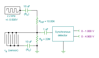
A small transmitter board interfaces with a microcontroller and conductivity probe to measure liquid conductance and conductivity. Precise equations and measurements are provided for this microcontroller-controlled conductivity meter.
The described circuit consists of a compact transmitter board that serves as an...

Flashflex Microcontroller Control Of Character Lcd Module
The FM497 is an integrated electronic ignition controller designed for breakerless ignition systems that utilize Hall effect sensors. This device operates an external NPN Darlington transistor to manage the coil current, thereby delivering the necessary stored energy while maintaining low...

Microcontroller interfacing with RS 232
Standard serial interfacing of a microcontroller (TTL) with a PC or any RS232C standard device requires a TTL to RS232 level converter. A MAX232 is used for this purpose. It provides a 2-channel RS232C port and requires external 10µF capacitors.
The...

5x7 DISPLAY
You must be able to recognise components such as capacitors, diodes, zeners, transistors and resistors to build a 5x7 Display project. This information is covered in our BASIC ELECTRONICS course and a complete set of circuit symbols can be found...

87C51 Selling Leads
This circuit utilizes an 87C57 microcontroller along with several peripherals to convert X-10 power-line carrier-code formats from a personal computer for use with an X-10 power-line interface in a home control system. Software details can be found in the reference....
Password Based Door Locking
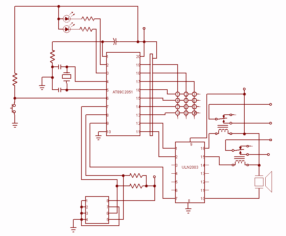
Security is a prime concern in our day-to-day life. Everyone wants to be as much secure as possible. An access control for doors forms a vital link in a security chain. The microcontroller based Door locker is an access control...

DC motor driver for DCMP(AVR-008)
A microcontroller is used to control various types of DC motors, including permanent magnet DC motors, DC servo motors, and stepper motors. This project utilizes the AVR-008 microcontroller from Circuits-Home, which is frequently referred to as the 3-in-1 driver motor...

Pots water alarm circuit
The flowers in pots require watering, as relying solely on the observation of moist soil surfaces can be unreliable. To address this issue, a flower watering indicator has been developed. This circuit includes a field effect transistor (VT1), a second...