


ISP Flash Microcontroller Programmer

Description: This ISP programmer can be utilized for in-system programming or as a standalone SPI programmer for Atmel ISP programmable devices. The programming interface is compatible with STK200 ISP programmer hardware, allowing users of STK200 to employ the software, which can program both the 8051 and AVR series devices. The circuit diagram of the in-system programmer interface is depicted in Figure 1. Power for the interface is supplied by the target system. The 74HCT541 IC isolates and buffers the parallel port signals. It is essential to use the HCT type IC to ensure compatibility with 3V type parallel ports.
The ISP programmer serves a dual purpose, functioning both as an in-system programmer and a standalone SPI programmer specifically designed for Atmel ISP programmable devices. Its compatibility with the STK200 ISP programmer hardware allows users to leverage existing software resources to program a range of devices, including those from the 8051 and AVR series.
The circuit diagram, referenced as Figure 1, illustrates the configuration of the in-system programmer interface. In this design, power is derived from the target system, which simplifies the setup and minimizes the need for additional power sources. This feature enhances the versatility of the programmer, making it suitable for various applications.
The inclusion of the 74HCT541 integrated circuit is a critical aspect of the design. This IC serves the dual functions of isolating and buffering the signals from the parallel port. The isolation protects the programmer and the target device from potential signal interference, while buffering ensures that the signals are adequately strengthened for reliable communication. The choice of the 74HCT541 is particularly significant, as it is designed to operate with both standard and low-voltage logic levels. Utilizing HCT type ICs is crucial in this context to maintain compatibility with 3V type parallel ports, thereby ensuring that the programmer can function correctly across a range of modern computing environments.
Overall, the described ISP programmer is a robust solution for programming Atmel devices, combining flexibility, compatibility, and reliability in its design.This ISP Programmer can be used either for in-system programming or as a stand-alone spi programmer for Atmel ISP programmable devices. The programming interface is compatible to STK200 ISP programmer hardware so the users of STK200 can also use the software which can program both the 8051 and AVR series devices.
Figure 1 shows the circuit diagram of the in-system programmer interface, the power to the interface is provided by the target system. The 74HCT541 ic isolate and buffer the parallel port signals. It is necessary to use the HCT type ic in order to make sure the programmer should also work with 3V type parallel port.
The ISP programmer serves a dual purpose, functioning both as an in-system programmer and a standalone SPI programmer specifically designed for Atmel ISP programmable devices. Its compatibility with the STK200 ISP programmer hardware allows users to leverage existing software resources to program a range of devices, including those from the 8051 and AVR series.
The circuit diagram, referenced as Figure 1, illustrates the configuration of the in-system programmer interface. In this design, power is derived from the target system, which simplifies the setup and minimizes the need for additional power sources. This feature enhances the versatility of the programmer, making it suitable for various applications.
The inclusion of the 74HCT541 integrated circuit is a critical aspect of the design. This IC serves the dual functions of isolating and buffering the signals from the parallel port. The isolation protects the programmer and the target device from potential signal interference, while buffering ensures that the signals are adequately strengthened for reliable communication. The choice of the 74HCT541 is particularly significant, as it is designed to operate with both standard and low-voltage logic levels. Utilizing HCT type ICs is crucial in this context to maintain compatibility with 3V type parallel ports, thereby ensuring that the programmer can function correctly across a range of modern computing environments.
Overall, the described ISP programmer is a robust solution for programming Atmel devices, combining flexibility, compatibility, and reliability in its design.This ISP Programmer can be used either for in-system programming or as a stand-alone spi programmer for Atmel ISP programmable devices. The programming interface is compatible to STK200 ISP programmer hardware so the users of STK200 can also use the software which can program both the 8051 and AVR series devices.
Figure 1 shows the circuit diagram of the in-system programmer interface, the power to the interface is provided by the target system. The 74HCT541 ic isolate and buffer the parallel port signals. It is necessary to use the HCT type ic in order to make sure the programmer should also work with 3V type parallel port.

avr Piezoelectric Sensor and the ADC
The intention is to utilize the sensor as a force sensor. It has been observed that the voltage output increases with the amount of pressure applied, although this output is only sustained for a brief period. This behavior is anticipated....
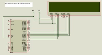
8051projects
This project demonstrates the use of the 8051 microcontroller to generate PWM outputs for two separate channels. The PWM signals can control the phase angle of SCRs or TRIACs for power regulation of AC loads such as heaters, motors, or...

AVR-P40-USB-8535 BOARD FOR AT90S8535
There are two ways to program AVR-P40-USB: with ICSP port and with JTAG port. To program via ICSP port you need serial port or parallel port AVR-ICSP programmer dongle (Olimex part # AVR-PG1B or AVR-PG2B). The serial port ICSP programmer...

led blinking using avr studio 5
This is a basic tutorial for beginners using the ATmega32 microcontroller to get started. This program can be referred to as a "Hello World" for the ATmega.
The ATmega32 microcontroller is a member of the AVR family, widely utilized in embedded...

digital room thermometer using lm35 sensor 8051 microcontroller
Interface the LCD with the 8051 microcontroller AT89S52. However, upon powering up the microcontroller, the LCD displays only black boxes. Multiple codes have been tried, but the output remains the same. The circuit has been simulated in Proteus, where the...
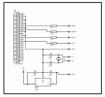
avr programmer
The following circuit diagram illustrates a very simple AVR microcontroller setup (source: unknown). It requires minimal components and is easy to construct on a general-purpose matrix PCB. PonyProg2000 software can be used to program the AVR microcontroller with this programmer....

avr Control 5V buzzer using mcu and a single 5 V power supply
A PB-12N23PW-05Q buzzer is being used with an ATmega 162 microcontroller. Direct connection to the microcontroller pin is not feasible due to the maximum sourcing capability of 20 mA as stated in the ATmega 162 datasheet, while the buzzer requires...

How to handle digital input/output(I/O) in Avr Microcontroller
How to handle digital input/output (I/O) in AVR microcontrollers is explained using basic programs and circuits to illuminate an LED, generate a stepper motor sequence, read a push-button switch, and implement key debouncing.
The handling of digital I/O in AVR microcontrollers...
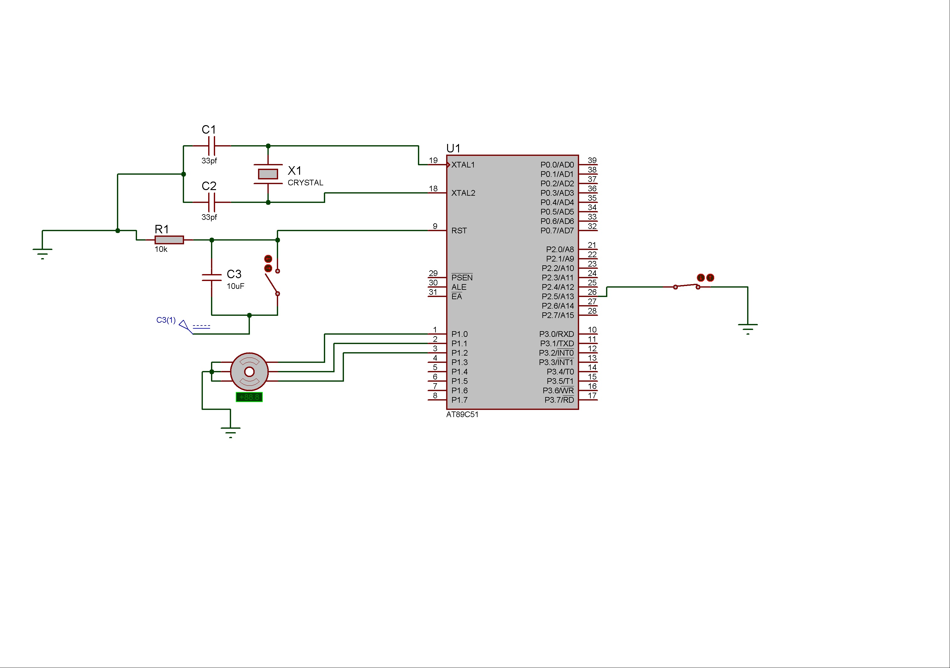
Controlling of Stepper Motor rotation in both direction using 8051 Microcontroller
Stepper motors consist of a permanent magnet rotating shaft, known as the rotor, and electromagnets on the stationary part that surrounds the motor, referred to as the stator. One complete rotation of a stepper motor is illustrated. At position 1,...