


Make Your Own USB Device using PIC18F4550
#PIC18F4550
#USB
#HID device
#firmware
#Windows interface
#LED control
#push-button
#tutorial
#breadboard
#embedded systems

Description: This tutorial provides guidance on creating a USB device, specifically a simple generic HID device using a breadboard. It covers the development of firmware for the PIC18F microcontroller and the creation of a Windows interface to control an LED and read the state of a push-button. The use of built-in drivers for generic HID devices simplifies the process of making compatible devices for Windows and Linux, eliminating the need for custom drivers and certificates. The project demonstrates basic two-way USB communication principles, paving the way for more complex projects. The circuit is constructed on a breadboard, utilizing the PIC18F4550 microcontroller, which is powered via the USB host. A 470nF capacitor is used to support the internal USB circuitry, and an ICSP header is included for programming. A 20MHz clock is necessary for USB applications, allowing the PIC to utilize PLL to achieve the required 48MHz for USB communication.
This project involves designing a USB generic Human Interface Device (HID) utilizing a breadboard setup, centered around the PIC18F4550 microcontroller. The tutorial begins by explaining the necessary components and their functions, followed by step-by-step instructions for assembling the circuit. The PIC18F4550 is chosen for its built-in USB capabilities, which facilitate direct communication with a host computer without the need for additional hardware.
The power for the device is supplied directly from the USB host, simplifying the circuit design as no external power regulation is required. The inclusion of a 470nF capacitor (C3) is crucial, as it stabilizes the voltage levels necessary for the microcontroller's internal USB circuitry, ensuring reliable operation during data transmission.
An In-Circuit Serial Programming (ICSP) header is integrated into the design, allowing for easy programming of the PIC18F4550. The PICkit2 programmer is recommended for its affordability and compatibility, although other ICSP-compatible programmers can also be utilized. This feature enables rapid development and debugging of the firmware.
For the firmware development, the MPLAB Integrated Development Environment (IDE) and the Hi-Tech C compiler are employed, both of which are freely available. This software will facilitate the creation of the necessary code to manage the USB communications, LED control, and button state reading.
On the software side, a Windows interface is developed using Microsoft Visual C++ 2008 Express, which allows users to interact with the device easily. This interface will provide controls for the LED and display the status of the push-button, reinforcing the principles of two-way USB communication.
The microcontroller operates at a base clock frequency of 20MHz, which is essential for USB applications. This clock speed is increased to 48MHz using Phase-Locked Loop (PLL) techniques within the microcontroller, enabling it to meet the USB communication requirements.
Overall, this project serves as an excellent introduction to USB device development, illustrating essential concepts in microcontroller programming, circuit design, and software interface creation. The knowledge gained from this experience can be applied to more advanced USB projects in the future.If you are looking to learn how to make your own USB device, this tutorial is perfect to start. Here you will see how to breadboard a simple USB generic HID device, creating the PIC18F firmware and finally creating the Windows interface for the device which will allow you to control a LED from the PC and read the state of a push-button from the de vice. Using the built in drivers for generic HID devices provides a simple method of creating Windows and Linux compatible devices and also makes the creation of both firmware and software far simpler. Since the HID standard does not require custom drivers you will not need to get a certificate for your driver, also both Windows and Linux have built-in libraries to help you communicate.
This project will allow you to control a LED from Windows and also see the status of a push-switch on the device. Using this the basic principals of 2-way USB communication will be made clear allowing you to progress onto more complex projects.
The circuit is made on a breadboard and the PIC18F firmware will be based on (the freely available) MPLAB and Hitech C compiler, the Windows software will be created using Microsoft Visual C+ 2008 express (which is also free to download). The circuit is very simple. The PIC18F4550 will be `bus powered`; this means that the device will draw its power from the USB host (your PC) so no power regulation is required.
The 470nF capacitor (C3) is required so the PIC can operate the internal USB circuitry (it helps with regulating the USB voltages required by the on-board USB interface in the PIC). The ICSP header allows you to connect a PIC programmer, I suggest using the inexpensive PICkit2 programmer, however other ICSP compatible programmers should work just fine.
The 20Mhz clock is required for USB applications. This allows the PIC to use PLL which ups the clock speed to the required 48Mhz necessary for USB communication.
This project involves designing a USB generic Human Interface Device (HID) utilizing a breadboard setup, centered around the PIC18F4550 microcontroller. The tutorial begins by explaining the necessary components and their functions, followed by step-by-step instructions for assembling the circuit. The PIC18F4550 is chosen for its built-in USB capabilities, which facilitate direct communication with a host computer without the need for additional hardware.
The power for the device is supplied directly from the USB host, simplifying the circuit design as no external power regulation is required. The inclusion of a 470nF capacitor (C3) is crucial, as it stabilizes the voltage levels necessary for the microcontroller's internal USB circuitry, ensuring reliable operation during data transmission.
An In-Circuit Serial Programming (ICSP) header is integrated into the design, allowing for easy programming of the PIC18F4550. The PICkit2 programmer is recommended for its affordability and compatibility, although other ICSP-compatible programmers can also be utilized. This feature enables rapid development and debugging of the firmware.
For the firmware development, the MPLAB Integrated Development Environment (IDE) and the Hi-Tech C compiler are employed, both of which are freely available. This software will facilitate the creation of the necessary code to manage the USB communications, LED control, and button state reading.
On the software side, a Windows interface is developed using Microsoft Visual C++ 2008 Express, which allows users to interact with the device easily. This interface will provide controls for the LED and display the status of the push-button, reinforcing the principles of two-way USB communication.
The microcontroller operates at a base clock frequency of 20MHz, which is essential for USB applications. This clock speed is increased to 48MHz using Phase-Locked Loop (PLL) techniques within the microcontroller, enabling it to meet the USB communication requirements.
Overall, this project serves as an excellent introduction to USB device development, illustrating essential concepts in microcontroller programming, circuit design, and software interface creation. The knowledge gained from this experience can be applied to more advanced USB projects in the future.If you are looking to learn how to make your own USB device, this tutorial is perfect to start. Here you will see how to breadboard a simple USB generic HID device, creating the PIC18F firmware and finally creating the Windows interface for the device which will allow you to control a LED from the PC and read the state of a push-button from the de vice. Using the built in drivers for generic HID devices provides a simple method of creating Windows and Linux compatible devices and also makes the creation of both firmware and software far simpler. Since the HID standard does not require custom drivers you will not need to get a certificate for your driver, also both Windows and Linux have built-in libraries to help you communicate.
This project will allow you to control a LED from Windows and also see the status of a push-switch on the device. Using this the basic principals of 2-way USB communication will be made clear allowing you to progress onto more complex projects.
The circuit is made on a breadboard and the PIC18F firmware will be based on (the freely available) MPLAB and Hitech C compiler, the Windows software will be created using Microsoft Visual C+ 2008 express (which is also free to download). The circuit is very simple. The PIC18F4550 will be `bus powered`; this means that the device will draw its power from the USB host (your PC) so no power regulation is required.
The 470nF capacitor (C3) is required so the PIC can operate the internal USB circuitry (it helps with regulating the USB voltages required by the on-board USB interface in the PIC). The ICSP header allows you to connect a PIC programmer, I suggest using the inexpensive PICkit2 programmer, however other ICSP compatible programmers should work just fine.
The 20Mhz clock is required for USB applications. This allows the PIC to use PLL which ups the clock speed to the required 48Mhz necessary for USB communication.
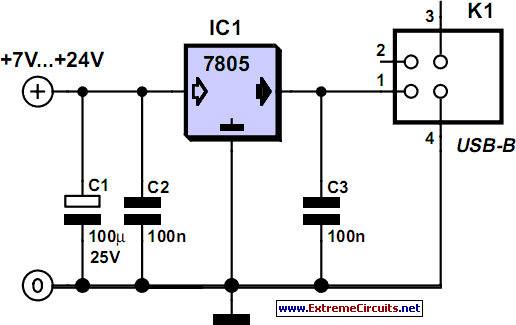
Power Supply For USB Devices
Although a matching charger is typically included in the package, some devices can only be charged via a USB port. This is not surprising for USB MP3 players, which need to dock with a PC for file transfers. However, this...

sensors circuits
All electronic circuits were initially built on breadboards. Once the circuits were operational, they were soldered onto perfboards to create a more durable system. A power board was designed to stack two batteries in series, providing access to a 14.4V...

electronic dice
This beginner's breadboard circuit simulates the action of throwing a dice. By pressing a button, the circuit generates a random output, lighting up one of six LEDs to represent the result of the throw.
The circuit utilizes a microcontroller or a...

usb switch schematic circuit
Individuals engaged in the experimentation or development of USB-connected peripheral hardware often find it frustrating to repeatedly disconnect and reconnect the plug to reestablish communication with the PC. This procedure is necessary, for instance, every time the peripheral device is...

A serial cradle
This project is aimed at building a small circuit that fits into a standard USB Visor cradle and that adds RS-232 capabilities. Note that Handspring sells a serial cradle but if you have more time than money, do it yourself...

USB I2C Interface
This kit is based on an original design by Jan G0BBL and serves as a versatile replacement for the older "Rocky" serial interface kit. It includes control of the programmable oscillator on the V6, 3 RXTX (and the older, now...

Secure USB Time-Stamp for Data-Logging
This project implements a USB device that provides a real-time clock for time-stamping events in a non-networked embedded computer environment. For embedded applications requiring periodic time-stamping (such as entry-system logs and configuration audit logs), an accurate real-time clock is necessary,...

USB Printer Share Switch
This device allows two computers to share a single USB printer or other USB devices, such as an external flash drive, memory card reader, or scanner. A rotary switch is used to select the PC that will use the USB...

basic circuit diagram design
Four switches will be connected to a USB joystick board. The USB board has +5V and ground connections and emulates a button press.
The circuit involves interfacing four mechanical switches with a USB joystick interface. The USB joystick board typically operates...