


microcontroller Analog to Digital Converter and Negative Voltages

Description: The ATtiny24 microcontroller's ADC is utilized to record an AC signal, which operates within a voltage range of 0 to 3.3V. A precision rectifier is employed to eliminate the negative portion of the signal. The circuit incorporates an LMC6484 operational amplifier powered by 3.3V on the V+ rail and 0V on the V- rail, along with 1N4004 diodes and 10kΩ resistors. The data logger successfully graphs the rectified waveform; however, an oscilloscope indicates that the rectifier's output fluctuates between -0.5V and 1V. In contrast, the microcontroller displays a signal with a similar waveform that ranges from 0V to 1.5V. When substituting the precision rectifier with a simple diode and resistor combination, the output waveform varies from -0.X volts to Y volts based on the input from a function generator. Although the microcontroller accurately tracks the waveform shape, the voltage range remains between 0.X and Y volts. There is a consistent presence of a slight negative signal, even with the precision rectifier, which causes the largest negative value to be shifted to zero in the logger's output, resulting in an extended range compared to the input. Positive voltages applied to the logger via a power supply are read accurately, and the waveform shapes are followed closely. The primary concern appears to be the voltage range, leading to confusion.
The circuit in question employs an ATtiny24 microcontroller with an integrated analog-to-digital converter (ADC) to measure an AC signal. The ADC's operational range is limited to 0-3.3V, necessitating the use of a precision rectifier to convert the AC signal into a suitable DC level for accurate measurement. The precision rectifier, based on the LMC6484 operational amplifier, is configured with the V+ rail connected to a 3.3V supply and the V- rail grounded. This configuration allows the op-amp to amplify the positive half-cycles of the AC signal while effectively eliminating the negative half-cycles.
The choice of 1N4004 diodes is appropriate for this application, as they provide reliable rectification with low forward voltage drop. The resistors used in the circuit, rated at 10kΩ, help set the gain of the op-amp and stabilize the output. Despite the intended design, the output observed on the oscilloscope indicates a voltage swing from -0.5V to 1V, which suggests that the precision rectifier is not entirely eliminating the negative voltages as expected. This discrepancy could be due to several factors, including the op-amp's output limitations or the diode's forward voltage characteristics.
The microcontroller's ADC displays a range of 0V to 1.5V, which indicates that the rectified signal is being processed correctly in terms of waveform shape; however, the voltage range does not align with the expected output. When a simple diode-resistor combination is tested, the output range shifts to -0.X to Y volts, demonstrating that the rectification method significantly impacts the resulting voltage levels.
The presence of a minor negative voltage in the output, even with the precision rectifier, suggests that there may be an offset in the circuit that needs to be addressed. The logger's ability to graph the results indicates that while the signal is being captured, the negative values are being shifted to zero, effectively expanding the range of the output compared to the input. The logger's performance with positive voltages confirms its accuracy in reading and tracking waveforms, indicating that the primary issue lies in the rectification process and the resulting voltage range.
To resolve these issues, a thorough review of the precision rectifier circuit is recommended, including checking for proper component values, ensuring the op-amp is functioning within its specifications, and verifying that the diodes are correctly oriented and operational. Adjustments to the circuit design may be necessary to achieve the desired performance and eliminate any unwanted negative voltages in the output.Using the ADC on an ATtiny24 to record a AC signal. The ADC has a range from 0-3. 3V. I`m using a precision rectifier to get rid of the negative portion of the signal. I`ve attached a picture of the circuit I`m using for the rectifier. I`m using an LMC6484 as the op-amp with 3. 3V to the V+ rail and 0 to the V- rail. I`m using 1N4004`s as the di odes and 10k for the resistors. My logger is able to graph the waveform of the rectifier very well. BUT the oscope shows that the output of the rectifier varies from -0. 5 to 1V. But my micro shows a signal with the same waveform that goes from 0-1. 5V! If I replace the precision rectifier with a simple diode/resistor combination, I get a waveform that varies from -0. X volts to Y volts (depending on the input through the function generator). The micro follows the shape of the waveform correctly but the voltage range is from 0. X to Y volts. I always have a little bit of a negative signal even with the precision rectifier and when I graph the results through my logger, it appears that the largest negative value has been moved up to zero, so I seem to get a larger range than the input.
I`ve input positive voltages into the logger through a power supply, and it reads those voltages perfectly! It follows the shape of the waveforms very well too. The only problem seems to be the range. I`m completely lost.
The circuit in question employs an ATtiny24 microcontroller with an integrated analog-to-digital converter (ADC) to measure an AC signal. The ADC's operational range is limited to 0-3.3V, necessitating the use of a precision rectifier to convert the AC signal into a suitable DC level for accurate measurement. The precision rectifier, based on the LMC6484 operational amplifier, is configured with the V+ rail connected to a 3.3V supply and the V- rail grounded. This configuration allows the op-amp to amplify the positive half-cycles of the AC signal while effectively eliminating the negative half-cycles.
The choice of 1N4004 diodes is appropriate for this application, as they provide reliable rectification with low forward voltage drop. The resistors used in the circuit, rated at 10kΩ, help set the gain of the op-amp and stabilize the output. Despite the intended design, the output observed on the oscilloscope indicates a voltage swing from -0.5V to 1V, which suggests that the precision rectifier is not entirely eliminating the negative voltages as expected. This discrepancy could be due to several factors, including the op-amp's output limitations or the diode's forward voltage characteristics.
The microcontroller's ADC displays a range of 0V to 1.5V, which indicates that the rectified signal is being processed correctly in terms of waveform shape; however, the voltage range does not align with the expected output. When a simple diode-resistor combination is tested, the output range shifts to -0.X to Y volts, demonstrating that the rectification method significantly impacts the resulting voltage levels.
The presence of a minor negative voltage in the output, even with the precision rectifier, suggests that there may be an offset in the circuit that needs to be addressed. The logger's ability to graph the results indicates that while the signal is being captured, the negative values are being shifted to zero, effectively expanding the range of the output compared to the input. The logger's performance with positive voltages confirms its accuracy in reading and tracking waveforms, indicating that the primary issue lies in the rectification process and the resulting voltage range.
To resolve these issues, a thorough review of the precision rectifier circuit is recommended, including checking for proper component values, ensuring the op-amp is functioning within its specifications, and verifying that the diodes are correctly oriented and operational. Adjustments to the circuit design may be necessary to achieve the desired performance and eliminate any unwanted negative voltages in the output.Using the ADC on an ATtiny24 to record a AC signal. The ADC has a range from 0-3. 3V. I`m using a precision rectifier to get rid of the negative portion of the signal. I`ve attached a picture of the circuit I`m using for the rectifier. I`m using an LMC6484 as the op-amp with 3. 3V to the V+ rail and 0 to the V- rail. I`m using 1N4004`s as the di odes and 10k for the resistors. My logger is able to graph the waveform of the rectifier very well. BUT the oscope shows that the output of the rectifier varies from -0. 5 to 1V. But my micro shows a signal with the same waveform that goes from 0-1. 5V! If I replace the precision rectifier with a simple diode/resistor combination, I get a waveform that varies from -0. X volts to Y volts (depending on the input through the function generator). The micro follows the shape of the waveform correctly but the voltage range is from 0. X to Y volts. I always have a little bit of a negative signal even with the precision rectifier and when I graph the results through my logger, it appears that the largest negative value has been moved up to zero, so I seem to get a larger range than the input.
I`ve input positive voltages into the logger through a power supply, and it reads those voltages perfectly! It follows the shape of the waveforms very well too. The only problem seems to be the range. I`m completely lost.

The Universal Linear Component
Operational amplifiers are the simplest and most effective means of executing a variety of linear functions, ranging from basic amplification to intricate analog computations.
Operational amplifiers (op-amps) are versatile components widely utilized in electronic circuits for various applications. These devices can...

Op-Amp Pulse Generator Circuits
Several operational amplifier circuits are presented here, configured as square wave oscillators. A square wave is a periodic pulse train with a 50 percent duty cycle. The operational amplifier functions as a high-gain amplifier, and oscillation is achieved with minimal...
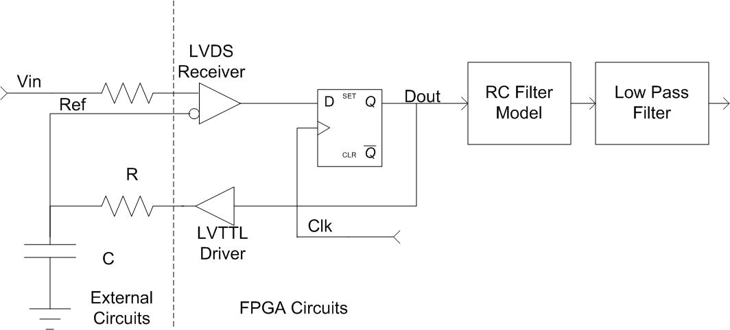
ADC In An FPGA
This content is highly technical and involves Analog-to-Digital Converters (ADCs), Field Programmable Gate Arrays (FPGAs), and advanced electrical design. If this topic does not resonate with you, it is advisable to skip the remainder of this blog post. An update:...

Refrigerator Pig
Upon opening your fridge door the photocell is exposed to light and the piggy oinks. Reverse engineered circuit diagram is of an early commercial design which uses an OP-AMP to make simulated pig sounds. Modern Fridge Pigs sound much better...

Operational amplifier
An operational amplifier, commonly referred to as an op-amp, is a DC-coupled high-gain electronic voltage amplifier featuring a differential input and typically a single-ended output. An op-amp generates an output voltage that is often millions of times larger than the...

Op Amp Classic Gain and Linearity Testing
The diagram below illustrates a classic test fixture that has been utilized for an extended period to assist individuals in addressing non-linearity errors.
The classic test fixture depicted in the diagram serves as a fundamental tool in electronics testing and calibration....

Simple Absolute Value Circuit
When the input voltage is positive, the output of ICA is negative, resulting in diode D not conducting; therefore, the output of ICB is positive. Conversely, when the input is negative, the output of ICA becomes positive. Diode D conducts,...

op amp A probably very easy Op-Amp Analysis
I have been measuring V_A = 15, which appears to be incorrect. Additionally, I believe V+ is equal to 0 since the node below the 3-ohm resistor is grounded. Assistance is needed to begin solving this. Initially, I set V+...
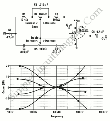
Single Op-Amp Tone Control
This is a single operational amplifier tone control circuit. The circuit functions as a hybrid low-pass, high-pass, and one-pole filter with both attenuation and gain.
The single op-amp tone control circuit utilizes an operational amplifier (op-amp) to manipulate audio signals by...