


microcontroller driving a relay with transistor and Opto-isolator
#stm32
#relay
#opto-isolator
#transistor
#gpio
#open drain
#microcontroller
#4N33
#MPS222
#isolation

Description: Controlling a relay with an STM32 microcontroller involves using a 4N33 opto-isolator for electrical isolation. The relay coil requires approximately 250 mA, necessitating the use of an MPS222 transistor for switching. The GPIO configuration inverts the logic when used as the source voltage for the opto-isolator LED. A pull-up resistor is employed, connecting the other end of the LED to the GPIO. The GPIO operates in open-drain mode, allowing around 3 mA to flow through the pin. Currently, the R2 resistor is not grounded. The concern arises that if the STM32 becomes disconnected, the relay may inadvertently activate, which is undesirable. The inquiry is whether adding the R2 resistor will resolve this issue.
The circuit described involves the integration of a relay control system utilizing an STM32 microcontroller, a 4N33 opto-isolator, and an MPS222 transistor. The STM32 microcontroller is programmed to control the relay via its GPIO pins. The 4N33 opto-isolator provides necessary electrical isolation between the microcontroller and the relay circuit, ensuring that any high voltages or currents do not affect the microcontroller's operation.
In the circuit, the relay coil requires a current of approximately 250 mA to operate effectively. The MPS222 transistor acts as a switching device, allowing the current to flow through the relay coil when activated by the opto-isolator. The opto-isolator's LED is driven by a GPIO pin configured in open-drain mode, which means it can only pull the line low and requires an external pull-up resistor to pull the line high when the GPIO is not active.
The issue of the relay inadvertently activating when the STM32 is disconnected is a critical consideration in circuit design. The absence of the R2 resistor, which is intended to provide a path to ground, can lead to undefined behavior in the circuit, potentially allowing the relay to turn on due to stray voltages or floating states on the GPIO pin. By adding the R2 resistor and properly grounding it, the GPIO pin can be pulled to a defined low state when the microcontroller is disconnected, thereby preventing the relay from being activated unintentionally.
In conclusion, the addition of the R2 resistor is a recommended solution to mitigate the risk of the relay turning on due to disconnection of the STM32 microcontroller. Implementing this change will enhance the reliability and safety of the relay control circuit.Controlling a relay with stm32 micro controller. For the isolation I have used a 4N33 opto-isolator. As my relay coil needs around 250 mA, I used a mps222 transistor. I figured that the logic gets inverted when I used the gpio as the source voltage for the opto-isolator led. I just used a pull up instead and connected the other end of the led part to the gpio. Gpio is open drain, I will drain around 3mA in the pin. I do not have the R2 resistor grounded at this moment. My problem is if in case my stm gets disconnected then my relay will be turned on - which I want to avoid. Could anyone please tell me if adding this R2 will fix the issue
The circuit described involves the integration of a relay control system utilizing an STM32 microcontroller, a 4N33 opto-isolator, and an MPS222 transistor. The STM32 microcontroller is programmed to control the relay via its GPIO pins. The 4N33 opto-isolator provides necessary electrical isolation between the microcontroller and the relay circuit, ensuring that any high voltages or currents do not affect the microcontroller's operation.
In the circuit, the relay coil requires a current of approximately 250 mA to operate effectively. The MPS222 transistor acts as a switching device, allowing the current to flow through the relay coil when activated by the opto-isolator. The opto-isolator's LED is driven by a GPIO pin configured in open-drain mode, which means it can only pull the line low and requires an external pull-up resistor to pull the line high when the GPIO is not active.
The issue of the relay inadvertently activating when the STM32 is disconnected is a critical consideration in circuit design. The absence of the R2 resistor, which is intended to provide a path to ground, can lead to undefined behavior in the circuit, potentially allowing the relay to turn on due to stray voltages or floating states on the GPIO pin. By adding the R2 resistor and properly grounding it, the GPIO pin can be pulled to a defined low state when the microcontroller is disconnected, thereby preventing the relay from being activated unintentionally.
In conclusion, the addition of the R2 resistor is a recommended solution to mitigate the risk of the relay turning on due to disconnection of the STM32 microcontroller. Implementing this change will enhance the reliability and safety of the relay control circuit.Controlling a relay with stm32 micro controller. For the isolation I have used a 4N33 opto-isolator. As my relay coil needs around 250 mA, I used a mps222 transistor. I figured that the logic gets inverted when I used the gpio as the source voltage for the opto-isolator led. I just used a pull up instead and connected the other end of the led part to the gpio. Gpio is open drain, I will drain around 3mA in the pin. I do not have the R2 resistor grounded at this moment. My problem is if in case my stm gets disconnected then my relay will be turned on - which I want to avoid. Could anyone please tell me if adding this R2 will fix the issue

touch switch circuit with 3 transistors
This document describes a series of touch switches that utilize only three transistors. These touch-based transistor switches can activate a load simply by the user touching a metal plate. They are designed to directly switch a relay, enabling operation with...

Anti-saturation function delete circuit schematics
Anti-saturation devices have been removed from the UAA4002 routine applications. The base current of the switching transistor, which is driven by another transistor, is automatically adjusted. This adjustment allows the power transistors to operate in critical saturation. However, when the...
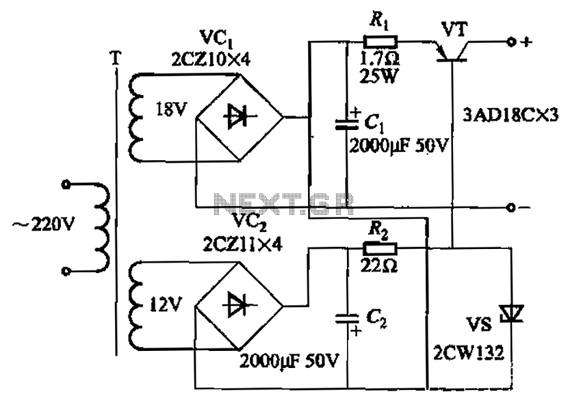
Steady flow of power transistor circuit
Characterized by a steady flow of power when the power supply voltage fluctuates or the load changes, this circuit maintains a constant load current. The output current of the circuit is illustrated in Figure 4A. When the load varies from...
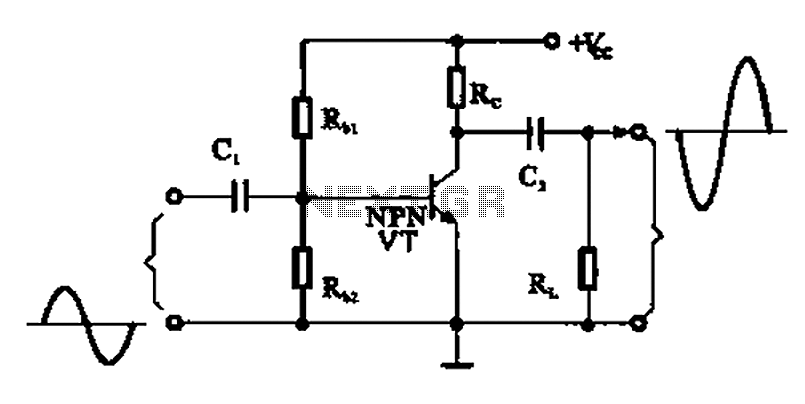
A common emitter amplifier
A common emitter amplifier is a total pole amplification circuit structure featuring a key emitting device. This circuit refers to the emitter of the input signal and the output signal connected to a common ground, forming the basis of fundamental...

audio tone control 2 transistor circuit
The first BC109C transistor functions as a buffer, delivering a high input impedance of approximately 250k and exhibiting a voltage gain marginally below unity. Given that the Baxendall tone control circuit operates passively, it attenuates all audio frequencies. The audio...
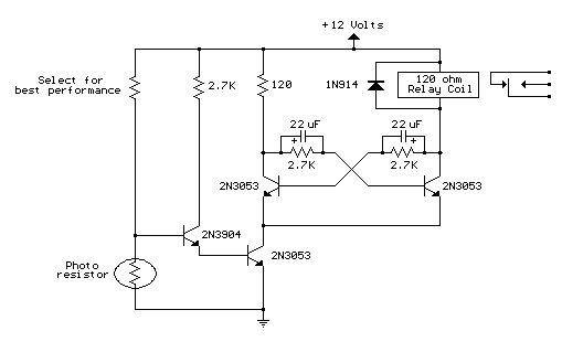
light activated relay
This circuit is similar to the previous one but incorporates a photoresistor to trigger the flip-flop instead of a push button. A bias resistor is placed in series with the photoresistor to ensure that adequate voltage is present at the...

darklight sensor using transistor
An automatic dark detector senses darkness. As the light level decreases and the light-dependent resistor (LDR) reaches the maximum threshold resistance, the circuit automatically activates the LED D1. Conversely, a light detector senses light, and when the light level increases...
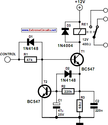
Energy Saver Relay Coil circuit and explanation
Some relays will become warm if they remain energized for some time. The circuit shown here will actuate the relay as before but then reduce the hold current through the relay coil by about 50%, thus considerably reducing the amount...

An adjustable bounce lighting circuit
A circuit involving oscillations is composed of a Houle Wang oscillator that utilizes a transistor configuration with components labeled Ti, n, and n, along with a composition of Q constants for the cycle. The waveform can be modified by changing...